
Brochure
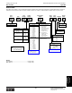

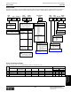
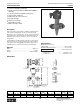
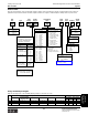
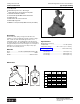
Table Of Contents
- MASTER TABLE of CONTENTS 1
- MASTER TABLE of CONTENTS 2ents 2
- CONTACT INFORMATION
- Cover
- Warning
- Your Preferred Supplier
- Value Added Services
- Value Added Parker Plus
- Residential AC Application
- Industrial Refrigeration Application
- Walk In Cooler Application
- Ice Machine Application
- Supermarket Application
- PHConnect
- EDI - Electronic Data Interchange
- Filter Dryer TOC
- Dryer Introduction
- Loose Filled Copper Dryers
- Loose Filled Spring Loaded Copper Dryers
- Service Copper Dryers
- Solid Core Copper Dryers
- Bi-Flow Copper Dryers
- Gold Label Steel Liquid Line Dryers
- Sahara Series Steel Liquid Line Dryers
- R410A Dryers
- BiFlow Stel Filter Dryers
- Gold Label Steel Suction Line Dryers
- Sahara Series Suction Line Dryers
- Dryer Shells and Cores
- Filter/Strainer/Oil Device TOC
- Accumulator, Receivers, Muffler TOC
- Sight Glass Moisture Indicator TOC
- Coupling TOC
- Service & Check Valve TOC
- TXV & AXV TOC
- Visual TOC 1
- Visual TOC 2
- S Series TXV
- I Series TXV
- EG Series TXV
- EGC Series TXV
- RE Series TXV
- H & HC Series TXV
- EC Series TXV
- ECC Series TXV
- G Series TXV
- N Series TXV
- C Series TXV
- B5 Series TXV
- PT Chart
- TXV Capacity Tables
- General TXV Information
- Valve Selection Procedure
- 104A & 104F Constant Pressure (AXV) Valves
- A Series Constant Pressure Valve (AXV)
- Model 139 Evaporator Pressure Regulator
- General Constant Pressure (AXV) Valve Information
- Model 625 Thermal Electric Valve
- Distributor & Flow Control TOC
- Refrigeration Solenoid Valves TOC
- R Series Refrigeration Solenoid Valves
- Introduction to Solenoid Valves
- Nomenclature
- General Specifications
- Ratings Summary
- R10 & R15 Series Solenoid Valves
- R20 & R25 Series Solenoid Valves
- R30 & R35 Solenoid Valves
- R40 & R45 Series Solenoid Valves
- R50 & R55 Series Solenoid Valves
- Electrical Specifications
- Coil Enclosures
- Capacity Tables
- Operating Principles
- Design Terminology
- Identification
- Agency Approvals
- Typical Applications
- 3-Way Hot Gas Defrost Valves
- Pulse Width Modulating Valves
- Secondary Coolant Solenoid Valves
- CROSS REFERENCE - R Series/Jackes Evans RB ORB
- Jackes Evans (RB/ORB Series)
- R Series Refrigeration Solenoid Valves
- General Purpose Solenoid Valves TOC
- FLO-CON Regulator & Valve TOC
- Overview
- (S)PORT & (S)PORT II Evaporator Pressure Regulators
- A8 Pressure Regulators
- A9 Pressure Regulators
- Suction Capacities A8, SPORT & SC
- A9 & A8 Condenser Bypass Capacities
- CK4 Check Valve
- Condenser Pressure Control
- Hot Gas Bypass
- Discharge Regulators for Supermarkets
- Crankcase Pressure Regulators
- SC Suction Solenoid Valves
- S81/S82 Solenoid Valves
- Abbreviations/Terminology
- Industrial Refrigeration TOC
- Warning/How to Use
- Pressure Regulators
- A2 Compact Regulators
- A2CK Relief Regulators
- A4 Adaptomode Regulators
- Weld End Regulators
- A2D Modular Presure Pilot
- S6A Modular Solenoid Pilot
- S6B Compact Modular Solenoid Pilot
- Modudapter
- Moduplate
- Vacuum Cartridge
- Outlet Regulator Kit
- Pressure Bonnet Kit
- Temperature Bonnet Kit
- Motor Bonnet Kit
- Electric Proportioning Thermostat
- Well, Separable
- Defrost Timer
- Handwheel
- Flange Ring-Tube Kits
- Class B Coil - S6A
- Class H Coil - S6B
- Voltages
- Solenoid Valves
- Gas Powered Suction Stop Valves
- Check Valves
- Safety Relief Valves
- Hand Valves
- Liquid Flow Regulators
- Refrigerant Float Switch
- Rapid Purger
- Automatic Liquid Drainer (ALD)
- Programmable Liquid Level Controller (PLLC)
- Flanges
- RS Strainers
- Liquid Drain Ball Valves
- Unibody Gauge Valves
- Gauges
- Depth Tracker Transducer Probes
- Open Refrigerant Pumps
- Hermetic Refrigerant Pumps
- Paint
- Warranties/Safe Operation
- Pressure in PSIG
- Pressure in Bar
- Offer of Sale
- Parker Hannifin Corporation
- Back Cover -CONTACT INFORMATION

Parker Hannifin Corporation
Climate & Industrial Controls Group
Cleveland, OH
Catalog CIC-2003-1/US
386
Industrial Refrigeration Products: Solenoid Valves
Type S5
●
Standard Coil Housing Meets NEMA 3R and
NEMA 4 – Rain Tight
●
Coil Housing Surpasses NEMA Salt Spray Test
●
Replaceable Piston Plug Assembly
●
Molded Class “B” Coil Construction
●
Pilot Light Available
●
Stainless Steel Needle
●
Manual Opening Stem
●
MOPD is 20.7 bar (300 PSIG);
MRP is 27.6 bar (400 PSIG)
Description
This heavy duty, pilot-operated, gravity closing solenoid
valve is suitable for ammonia and other common refriger-
ants, certain oils and other fluids approved for use in
refrigeration. The valve may be opened by means of a
manual opening stem for servicing or in case of electrical
power failure. The valve can be ordered with a close-
coupled stainless steel screen strainer (see page 436).
Materials
Body ..................................................................... Gray Iron
Seat
32mm (1¼") ........................................................... PTFE
40-75mm (1
5
⁄8" - 3") ................................................ Metal
Needle......................................................... Stainless Steel
Specifications
Minimum Pressure Drop
to Open Wide ............................................ 0.07 bar (1 PSI)
Minimum Fluid Temperature ......................... -30°C (-25°F)
Coil (see page 394) .............................. Class “B” Housing
External Connection
for Outlet Pressure (S5E) ...................................... ¼" FPT
Flow Coefficients
32mm (1¼") .................................... 16.3 Kv (19.0 Cv)
40 mm (1
5
⁄8") ................................... 31.7 Kv (37.0 Cv)
50 mm (2") ...................................... 43.7 Kv (51.0 Cv)
65mm (2½") .................................... 70.7 Kv (82.0 Cv)
75mm (3") ........................................ 98.0 Kv (115 Cv)
PORT SIZE
32mm 40 & 50mm 65mm 75mm
Dimension (1-1/4") (1-5/8" & 2") (2-1/2") (3")
A mm 348 411 437 511
inch 13.7 16.2 17.2 20.1
B mm 117 127 137 198
inch 4.6 5.0 5.4 7.8
C mm 203 251 251 311
inch 8.0 9.9 9.9 12.2
D mm 256 307 331 289
(FPT,SW) inch 10.1 12.1 13.0 15.3
1-1/4 1-1/2 1-1/2 2
E mm 300 304 364 371 401 478
(WN) inch 11.8 12.0 14.3 14.6 15.8 18.8
1-3/8 1-5/8 2-1/8 1-5/8 2-1/8 2-5/8 2-5/8 3-1/8 3-1/8 3-5/8
F mm 269 279 304 358 338 358 348 389 414 432
(ODS) inch 10.6 11.0 12.0 14.1 13.3 14.1 13.7 15.3 16.3 17.0
G mm 178 251 314 314
inch 7.0 9.9 12.4 12.4
H mm 117 140 159 176
inch 4.6 5.5 6.2 7.0
J mm 231 284 300 312
inch 9.1 11.2 11.8 12.3
1-3/8 1-5/8 2-1/8 1-5/8 2-1/8 2-5/8 2-5/8 3-1/8 3-1/8 3-5/8
N mm2528 332833 38 38 43 43 48
(ODS) inch 1.0 1.1 1.3 1.1 1.3 1.5 1.5 1.7 1.7 1.9
1-1/4 1-1/2 1-1/2 2
Pmm15 15 15 15 25 29
(SW) inch 0.6 0.6 0.6 0.6 1.0 1.1
J
A
B
C
D
SW
FPT
G
N
F
H
MAX.
P
F. P. T.
OR S.W.
O.D.S. SOLDER
FLANGES
WELD NECK
FLANGES
E
BETWEEN
TUBE
STOPS
ADD FOR
STRAINER
Dimensions
Technical Information