
Brochure
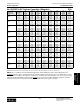
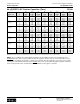

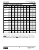
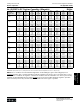


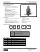

Table Of Contents
- MASTER TABLE of CONTENTS 1
- MASTER TABLE of CONTENTS 2ents 2
- CONTACT INFORMATION
- Cover
- Warning
- Your Preferred Supplier
- Value Added Services
- Value Added Parker Plus
- Residential AC Application
- Industrial Refrigeration Application
- Walk In Cooler Application
- Ice Machine Application
- Supermarket Application
- PHConnect
- EDI - Electronic Data Interchange
- Filter Dryer TOC
- Dryer Introduction
- Loose Filled Copper Dryers
- Loose Filled Spring Loaded Copper Dryers
- Service Copper Dryers
- Solid Core Copper Dryers
- Bi-Flow Copper Dryers
- Gold Label Steel Liquid Line Dryers
- Sahara Series Steel Liquid Line Dryers
- R410A Dryers
- BiFlow Stel Filter Dryers
- Gold Label Steel Suction Line Dryers
- Sahara Series Suction Line Dryers
- Dryer Shells and Cores
- Filter/Strainer/Oil Device TOC
- Accumulator, Receivers, Muffler TOC
- Sight Glass Moisture Indicator TOC
- Coupling TOC
- Service & Check Valve TOC
- TXV & AXV TOC
- Visual TOC 1
- Visual TOC 2
- S Series TXV
- I Series TXV
- EG Series TXV
- EGC Series TXV
- RE Series TXV
- H & HC Series TXV
- EC Series TXV
- ECC Series TXV
- G Series TXV
- N Series TXV
- C Series TXV
- B5 Series TXV
- PT Chart
- TXV Capacity Tables
- General TXV Information
- Valve Selection Procedure
- 104A & 104F Constant Pressure (AXV) Valves
- A Series Constant Pressure Valve (AXV)
- Model 139 Evaporator Pressure Regulator
- General Constant Pressure (AXV) Valve Information
- Model 625 Thermal Electric Valve
- Distributor & Flow Control TOC
- Refrigeration Solenoid Valves TOC
- R Series Refrigeration Solenoid Valves
- Introduction to Solenoid Valves
- Nomenclature
- General Specifications
- Ratings Summary
- R10 & R15 Series Solenoid Valves
- R20 & R25 Series Solenoid Valves
- R30 & R35 Solenoid Valves
- R40 & R45 Series Solenoid Valves
- R50 & R55 Series Solenoid Valves
- Electrical Specifications
- Coil Enclosures
- Capacity Tables
- Operating Principles
- Design Terminology
- Identification
- Agency Approvals
- Typical Applications
- 3-Way Hot Gas Defrost Valves
- Pulse Width Modulating Valves
- Secondary Coolant Solenoid Valves
- CROSS REFERENCE - R Series/Jackes Evans RB ORB
- Jackes Evans (RB/ORB Series)
- R Series Refrigeration Solenoid Valves
- General Purpose Solenoid Valves TOC
- FLO-CON Regulator & Valve TOC
- Overview
- (S)PORT & (S)PORT II Evaporator Pressure Regulators
- A8 Pressure Regulators
- A9 Pressure Regulators
- Suction Capacities A8, SPORT & SC
- A9 & A8 Condenser Bypass Capacities
- CK4 Check Valve
- Condenser Pressure Control
- Hot Gas Bypass
- Discharge Regulators for Supermarkets
- Crankcase Pressure Regulators
- SC Suction Solenoid Valves
- S81/S82 Solenoid Valves
- Abbreviations/Terminology
- Industrial Refrigeration TOC
- Warning/How to Use
- Pressure Regulators
- A2 Compact Regulators
- A2CK Relief Regulators
- A4 Adaptomode Regulators
- Weld End Regulators
- A2D Modular Presure Pilot
- S6A Modular Solenoid Pilot
- S6B Compact Modular Solenoid Pilot
- Modudapter
- Moduplate
- Vacuum Cartridge
- Outlet Regulator Kit
- Pressure Bonnet Kit
- Temperature Bonnet Kit
- Motor Bonnet Kit
- Electric Proportioning Thermostat
- Well, Separable
- Defrost Timer
- Handwheel
- Flange Ring-Tube Kits
- Class B Coil - S6A
- Class H Coil - S6B
- Voltages
- Solenoid Valves
- Gas Powered Suction Stop Valves
- Check Valves
- Safety Relief Valves
- Hand Valves
- Liquid Flow Regulators
- Refrigerant Float Switch
- Rapid Purger
- Automatic Liquid Drainer (ALD)
- Programmable Liquid Level Controller (PLLC)
- Flanges
- RS Strainers
- Liquid Drain Ball Valves
- Unibody Gauge Valves
- Gauges
- Depth Tracker Transducer Probes
- Open Refrigerant Pumps
- Hermetic Refrigerant Pumps
- Paint
- Warranties/Safe Operation
- Pressure in PSIG
- Pressure in Bar
- Offer of Sale
- Parker Hannifin Corporation
- Back Cover -CONTACT INFORMATION

Flo-Con Pressure Regulators and Valves
Parker Hannifin Corporation
Climate & Industrial Controls Group
Cleveland, OH
299
Catalog CIC-2003-1/US
Flo-Con Pressure
Regulators
& Valves
Installation: For those A8 regulators having an intregal
pilot solenoid feature, the solenoid operators utilize a
spring loaded solenoid plunger design, which assists
the plunger in closing off tightly against the solenoid
pilot seat regardless of position or orientation. The
regulator can therefore be installed in either a horizon-
tal or vertical pipe line regardless of valve variation.
Those A8 regulators that have no pilot solenoid can
also be installed in a similar manner.
When brazing in line, typically a wet cloth wrapped
around the valve body is recommended to dissipate
heat. If a valve is disassembled prior to installation,
always have the correct gasket/ O-ring kit available
for reassembly. The internal cartridge-to-body O-ring
will need to be replaced prior to reassembly.
Adjustment: Adjustment of a regulator's set point re-
quires that the pressure being controlled be monitored
by an accurate pressure gauge. Turning the valve's ad-
justing screw clockwise (into the bonnet) compresses
the range spring and subsequently raises the valves
set point. Conversely, turning the adjusting stem
counter-clockwise will decrease the valve's set point.
Adjusting the set point of an A8AS, A81S, or A82S
regulator must be made with the solenoid energized,
and the manual opening stem turned in . The adjust-
ment of an A8AB, A81B, or A82B must be made with
the solenoid de-energized, and the manual opening
stem turned in.
Electrical: All A8 regulator versions utilize a molded
water resistant class “H” solenoid coil with a “general
purpose” coil housing as standard. A class “H” DIN
coil is also available with certain voltages. Coils are
designed to operate with line voltage from 85% to
110% of rated coil voltage. Operating with a coil voltage
above or below these limits may result in coil burnout.
Also, operating with a coil voltage below this limit will
result in lowering the valves' maximum opening pres-
sure differential, or MOPD.
Ordering Guide: Specify valve type, port and connec-
tion size, and voltage, if applicable.
Technical Information A8 Pressure Regulators
Description/Variations: A8 Pressure regulators can
conveniently be identified by three primary types: inlet,
outlet, and differential regulator versions. Inlet pressure
regulators open on a rise in inlet pressure above the
valves set point, and close when the inlet pressure
drops below the valve's set point.
Outlet pressure regulators maintain a constant outlet or
downstream pressure. Outlet regulators will open when
outlet pressure falls below the valves set point and
close when the outlet pressure is above it’s set point.
Differential pressure regulators will open when the
pressure difference across the regulator is greater than
the valves set point. Conversely, they will close when
the pressure difference across the valve is below the
valve's set point.
In addition, these three categories of valves, inlet,
outlet, and differential, can also have optional variations
added to the basic regulator, such as an electric shut-
off feature, or bypass (electric wide opening) feature.
Please refer to the inside front cover of this condensed
catalog for a complete listing of all A8 regulator varia-
tions and their typical applications.
Pressure Ranges: All A8 series inlet and outlet
pressure regulators feature a wide pressure range, 10"
Hg to 400 psig (250mm Hg to 27.6 bar), thus allowing
flexibility in application. Differential pressure regulators
offer a single range spring capable of being set within
a range of 0 to 120 psig (0 to 8.3 bar). Since it is the
pressure difference across the valve which is being
controlled with any differential regulator version (not
inlet pressure), this range is appropriate for any appli-
cation, whether applied on the low side or high side of
the system. For example, discharge regulators will
certainly be exposed to pressures exceeding 120 psig
under normal operation. However, they are most typi-
cally set to control at about a 25 psi differential for hot
gas supply purposes for defrost. Since this 25 psi set
point easily falls within the range of this regulator, it is
an appropriate pressure range for the application.
NOTE: For A8 valve suction capacity tables, please reference pages 290-297 of this catalog.