
Brochure
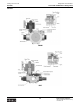
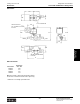
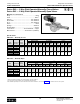
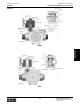
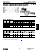

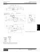

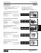
Table Of Contents
- MASTER TABLE of CONTENTS 1
- MASTER TABLE of CONTENTS 2ents 2
- CONTACT INFORMATION
- Cover
- Warning
- Your Preferred Supplier
- Value Added Services
- Value Added Parker Plus
- Residential AC Application
- Industrial Refrigeration Application
- Walk In Cooler Application
- Ice Machine Application
- Supermarket Application
- PHConnect
- EDI - Electronic Data Interchange
- Filter Dryer TOC
- Dryer Introduction
- Loose Filled Copper Dryers
- Loose Filled Spring Loaded Copper Dryers
- Service Copper Dryers
- Solid Core Copper Dryers
- Bi-Flow Copper Dryers
- Gold Label Steel Liquid Line Dryers
- Sahara Series Steel Liquid Line Dryers
- R410A Dryers
- BiFlow Stel Filter Dryers
- Gold Label Steel Suction Line Dryers
- Sahara Series Suction Line Dryers
- Dryer Shells and Cores
- Filter/Strainer/Oil Device TOC
- Accumulator, Receivers, Muffler TOC
- Sight Glass Moisture Indicator TOC
- Coupling TOC
- Service & Check Valve TOC
- TXV & AXV TOC
- Visual TOC 1
- Visual TOC 2
- S Series TXV
- I Series TXV
- EG Series TXV
- EGC Series TXV
- RE Series TXV
- H & HC Series TXV
- EC Series TXV
- ECC Series TXV
- G Series TXV
- N Series TXV
- C Series TXV
- B5 Series TXV
- PT Chart
- TXV Capacity Tables
- General TXV Information
- Valve Selection Procedure
- 104A & 104F Constant Pressure (AXV) Valves
- A Series Constant Pressure Valve (AXV)
- Model 139 Evaporator Pressure Regulator
- General Constant Pressure (AXV) Valve Information
- Model 625 Thermal Electric Valve
- Distributor & Flow Control TOC
- Refrigeration Solenoid Valves TOC
- R Series Refrigeration Solenoid Valves
- Introduction to Solenoid Valves
- Nomenclature
- General Specifications
- Ratings Summary
- R10 & R15 Series Solenoid Valves
- R20 & R25 Series Solenoid Valves
- R30 & R35 Solenoid Valves
- R40 & R45 Series Solenoid Valves
- R50 & R55 Series Solenoid Valves
- Electrical Specifications
- Coil Enclosures
- Capacity Tables
- Operating Principles
- Design Terminology
- Identification
- Agency Approvals
- Typical Applications
- 3-Way Hot Gas Defrost Valves
- Pulse Width Modulating Valves
- Secondary Coolant Solenoid Valves
- CROSS REFERENCE - R Series/Jackes Evans RB ORB
- Jackes Evans (RB/ORB Series)
- R Series Refrigeration Solenoid Valves
- General Purpose Solenoid Valves TOC
- FLO-CON Regulator & Valve TOC
- Overview
- (S)PORT & (S)PORT II Evaporator Pressure Regulators
- A8 Pressure Regulators
- A9 Pressure Regulators
- Suction Capacities A8, SPORT & SC
- A9 & A8 Condenser Bypass Capacities
- CK4 Check Valve
- Condenser Pressure Control
- Hot Gas Bypass
- Discharge Regulators for Supermarkets
- Crankcase Pressure Regulators
- SC Suction Solenoid Valves
- S81/S82 Solenoid Valves
- Abbreviations/Terminology
- Industrial Refrigeration TOC
- Warning/How to Use
- Pressure Regulators
- A2 Compact Regulators
- A2CK Relief Regulators
- A4 Adaptomode Regulators
- Weld End Regulators
- A2D Modular Presure Pilot
- S6A Modular Solenoid Pilot
- S6B Compact Modular Solenoid Pilot
- Modudapter
- Moduplate
- Vacuum Cartridge
- Outlet Regulator Kit
- Pressure Bonnet Kit
- Temperature Bonnet Kit
- Motor Bonnet Kit
- Electric Proportioning Thermostat
- Well, Separable
- Defrost Timer
- Handwheel
- Flange Ring-Tube Kits
- Class B Coil - S6A
- Class H Coil - S6B
- Voltages
- Solenoid Valves
- Gas Powered Suction Stop Valves
- Check Valves
- Safety Relief Valves
- Hand Valves
- Liquid Flow Regulators
- Refrigerant Float Switch
- Rapid Purger
- Automatic Liquid Drainer (ALD)
- Programmable Liquid Level Controller (PLLC)
- Flanges
- RS Strainers
- Liquid Drain Ball Valves
- Unibody Gauge Valves
- Gauges
- Depth Tracker Transducer Probes
- Open Refrigerant Pumps
- Hermetic Refrigerant Pumps
- Paint
- Warranties/Safe Operation
- Pressure in PSIG
- Pressure in Bar
- Offer of Sale
- Parker Hannifin Corporation
- Back Cover -CONTACT INFORMATION

Parker Hannifin Corporation
Climate & Industrial Controls Group
Cleveland, OH
Catalog CIC-2003-1/US
Refrigeration Solenoid Valves
248
Technical Information Electrical Specifications
Electrical Specifications
All Parker Refrigeration solenoid valves use standard
coil designs that are interchangeable on all valve
bodies. They are available in a wide variety of standard
voltages and frequencies. Coils are labeled with electri-
cal data providing easy identification.
Construction
Numerous construction options are available including
junction box housing, DIN terminals, conduit hub
housing and spade termination coils.
Encapsulated waterproof coils are standard on all
valves listed in the catalog. The special compound is
absolutely waterproof and impervious to oil, dust and
most corrosive fumes and vapors.
All coils are Class “F” or “H” rated for high temperature
application requirements. The coils are molded in
accordance with UL, NEMA, and other accepted
standards.
Standard Coil Options
trates which wires to connect to each other for 120 or
240 volt operation. Wiring and fusing must comply
with prevailing local and national wiring codes and
ordinances.
Electrical Supply Requirements
The solenoid coil must be connected to electrical lines
of correct voltage and frequency as indicated on the
coil label. The supply circuits must be properly sized to
give adequate voltage at the coil leads even when other
electrical equipment is operating. The molded coil is de-
signed to operate with line voltage from 85% to 110%
of the coil rated voltage. Operating with a line voltage
above or below these limits may result in reduced coil
life or coil burn out. Also, operating with line voltage be-
low the limit will result in lowering the maximum operat-
ing pressure differential (MOPD).
Wiring
Check the electrical specifications of the coil to make
sure they correspond to the available electrical service.
Valves with four-wire dual voltage option have a wiring
diagram shown in the following figure. The figure illus-
Wiring for Dual-Voltage Coil
Conversion from AC to DC Coils
The same valve assembly can be used for both AC
and DC service requirements. AC and DC coils are
interchangeable. To convert a valve assembly from AC
to DC service, select the appropriate DC coil wattage
and voltage per the valve specification chart based on
the system pressure requirements.
Electrical Data
To determine the approximate Holding or Inrush Cur-
rent for AC voltages including 24/60, 120/60, 208/60
and 240/60 in amperes, divide the voltage into the VA
rating indicated in the AC Power Consumption tables.
DC valves have no inrush current. The current rating in
amperes are shown in the DC table. Figures are based
on nominal values and will vary slightly depending on
operating voltage and coil tolerances.
VA
Holding
VA
Inrush
VA
Holding
VA
Inrush
R10 Series 18 37 38 68
R20 Series 19 43 40 78
R30 Series 19 32 42 59
R40 Series 19 32 42 59
R50 Series 18 37 38 68
R15 Series 17 33 42 63
R25 Series 16 33 42 63
R35 Series 16 33 42 63
R45 Series 16 33 42 63
R55 Series 17 33 42 63
AC Power Consumption Ratings
10 watt Coils 22 watt Coils
Valve Series
Normally Closed Valves
Normally Open Valves
Coil
Type 12 VDC 24 VDC
R25 Series 16 33
R35 Series 16 33
R45 Series 16 33
R55 Series 17 33
DC Current Comsumption Ratings (Amperes)
Coil
Type
Standard
Termination Protection
Junction Box 6” lead length
Junction box equipped with
grounding screw provision
Conduit Hub
18” lead length
2-wires
Type 1,2,3,3S,4,4X
DIN
DIN
(terminations per
DIN 43650/ISO 4400
requirements)
Cable glad or 1/2" NPT
connectors available
for IP65 protection
Leaded
18" Lead length
2-wires
Open frame enclosure
where suitable
Spade 1/4" Male
Open frame enclosure
where suitable