
Brochure
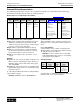
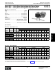


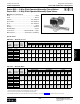
Table Of Contents
- MASTER TABLE of CONTENTS 1
- MASTER TABLE of CONTENTS 2ents 2
- CONTACT INFORMATION
- Cover
- Warning
- Your Preferred Supplier
- Value Added Services
- Value Added Parker Plus
- Residential AC Application
- Industrial Refrigeration Application
- Walk In Cooler Application
- Ice Machine Application
- Supermarket Application
- PHConnect
- EDI - Electronic Data Interchange
- Filter Dryer TOC
- Dryer Introduction
- Loose Filled Copper Dryers
- Loose Filled Spring Loaded Copper Dryers
- Service Copper Dryers
- Solid Core Copper Dryers
- Bi-Flow Copper Dryers
- Gold Label Steel Liquid Line Dryers
- Sahara Series Steel Liquid Line Dryers
- R410A Dryers
- BiFlow Stel Filter Dryers
- Gold Label Steel Suction Line Dryers
- Sahara Series Suction Line Dryers
- Dryer Shells and Cores
- Filter/Strainer/Oil Device TOC
- Accumulator, Receivers, Muffler TOC
- Sight Glass Moisture Indicator TOC
- Coupling TOC
- Service & Check Valve TOC
- TXV & AXV TOC
- Visual TOC 1
- Visual TOC 2
- S Series TXV
- I Series TXV
- EG Series TXV
- EGC Series TXV
- RE Series TXV
- H & HC Series TXV
- EC Series TXV
- ECC Series TXV
- G Series TXV
- N Series TXV
- C Series TXV
- B5 Series TXV
- PT Chart
- TXV Capacity Tables
- General TXV Information
- Valve Selection Procedure
- 104A & 104F Constant Pressure (AXV) Valves
- A Series Constant Pressure Valve (AXV)
- Model 139 Evaporator Pressure Regulator
- General Constant Pressure (AXV) Valve Information
- Model 625 Thermal Electric Valve
- Distributor & Flow Control TOC
- Refrigeration Solenoid Valves TOC
- R Series Refrigeration Solenoid Valves
- Introduction to Solenoid Valves
- Nomenclature
- General Specifications
- Ratings Summary
- R10 & R15 Series Solenoid Valves
- R20 & R25 Series Solenoid Valves
- R30 & R35 Solenoid Valves
- R40 & R45 Series Solenoid Valves
- R50 & R55 Series Solenoid Valves
- Electrical Specifications
- Coil Enclosures
- Capacity Tables
- Operating Principles
- Design Terminology
- Identification
- Agency Approvals
- Typical Applications
- 3-Way Hot Gas Defrost Valves
- Pulse Width Modulating Valves
- Secondary Coolant Solenoid Valves
- CROSS REFERENCE - R Series/Jackes Evans RB ORB
- Jackes Evans (RB/ORB Series)
- R Series Refrigeration Solenoid Valves
- General Purpose Solenoid Valves TOC
- FLO-CON Regulator & Valve TOC
- Overview
- (S)PORT & (S)PORT II Evaporator Pressure Regulators
- A8 Pressure Regulators
- A9 Pressure Regulators
- Suction Capacities A8, SPORT & SC
- A9 & A8 Condenser Bypass Capacities
- CK4 Check Valve
- Condenser Pressure Control
- Hot Gas Bypass
- Discharge Regulators for Supermarkets
- Crankcase Pressure Regulators
- SC Suction Solenoid Valves
- S81/S82 Solenoid Valves
- Abbreviations/Terminology
- Industrial Refrigeration TOC
- Warning/How to Use
- Pressure Regulators
- A2 Compact Regulators
- A2CK Relief Regulators
- A4 Adaptomode Regulators
- Weld End Regulators
- A2D Modular Presure Pilot
- S6A Modular Solenoid Pilot
- S6B Compact Modular Solenoid Pilot
- Modudapter
- Moduplate
- Vacuum Cartridge
- Outlet Regulator Kit
- Pressure Bonnet Kit
- Temperature Bonnet Kit
- Motor Bonnet Kit
- Electric Proportioning Thermostat
- Well, Separable
- Defrost Timer
- Handwheel
- Flange Ring-Tube Kits
- Class B Coil - S6A
- Class H Coil - S6B
- Voltages
- Solenoid Valves
- Gas Powered Suction Stop Valves
- Check Valves
- Safety Relief Valves
- Hand Valves
- Liquid Flow Regulators
- Refrigerant Float Switch
- Rapid Purger
- Automatic Liquid Drainer (ALD)
- Programmable Liquid Level Controller (PLLC)
- Flanges
- RS Strainers
- Liquid Drain Ball Valves
- Unibody Gauge Valves
- Gauges
- Depth Tracker Transducer Probes
- Open Refrigerant Pumps
- Hermetic Refrigerant Pumps
- Paint
- Warranties/Safe Operation
- Pressure in PSIG
- Pressure in Bar
- Offer of Sale
- Parker Hannifin Corporation
- Back Cover -CONTACT INFORMATION

Parker Hannifin Corporation
Climate & Industrial Controls Group
Cleveland, OH
Catalog CIC-2003-1/US
Refrigeration Solenoid Valves
230
Ordering Instructions & Standard Voltages General Information
Solenoid Valve Nomenclature
The numbering system allows every user an easy method to identify, select and understand the valve being
purchased. The following table describes the numbering system
Nomenclature for Complete Valve Assemblies:
For combined Valve and Coil Assemblies:
Step 1: Select the Valve catalog number based on the
application requirements as specified in the indi-
vidual catalog section based on the connection type,
port size, connection size and rating.
Step 2: Add the optional Manual Stem, if required.
Step 3: Select the appropriate coil type and wattage
per the valve specification chart based on the sys-
tem pressures. Either 10 watt or 22 watt coil.
Step 4: Use the Voltage Code to specify the correct
voltage.
Example:
Step 1 & 2: To order a 2-way normally closed valve, 1/2
ODF connection, manual bypass option, R22, 5 ton
liquid line rating, reference R20 valve catalog page.
Select R20E84M.
Step 3 & 4: To order a junction box coil assembly, 10W,
208-240VAC rating, reference coil assembly catalog
page. Select K1U3.
To order fully assembled valve with coil, simply add the
2 part numbers together.
Example: R20E84M + K1U3 = R20E84MK1U3
For Valves Only:
Valve assemblies can be ordered as separate items.
Simply select the catalog valve number in steps 1 & 2
above.
For Coil Assemblies:
Coil Assemblies can be ordered as separate items.
Simply begin the coil assembly part number using an
“R” and follow steps 3 & 4 above.
Example: To select a junction box coil assembly,
10W, 208-240VAC rating, reference coil assembly
catalog page. Specify RK1U3.
Standard Voltages
Voltage
Code
DC
Voltage
Voltage
Code
AC
Voltage
C1 12 VDC B2 24/60
C2 24 VDC P3 120/60; 110/50
2K 208/60
Q3 240/60; 220/50
U3 208-240/60
Consult Parker for additional voltages that can be satis-
fied with a new coil of a specific voltage.
Type
Family
Configuration Connection Port Size
Connection
Size
Optional
Manual Stem Coil Type
Coil
Watts Voltage Codes
R
Refrigeration
10
20
30
40
50
E – Ext End
F – Flare
Port sizes
are measured
in 1/32nds of
an inch
Connection
sizes are
measured in
1/8ths of an
inch
MD – Din
J – Leaded
K – Junction Box
T – Spade
C – Conduit Hub
1-10
3-22
C1 12VDC
C2 24VDC
B2 24/60
2K 208/60
P3 120/60
Q3 240/60
U3 208-240/60
(Reference electrical
enclosure catalog page
for a detailed description
of each coil type)
(Reference standard
voltages for a
detailed description
of each code)
Valve Assemblies Electrical Enclosures