
Brochure


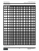
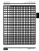
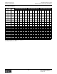
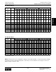
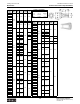

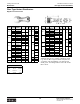
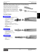
Table Of Contents
- MASTER TABLE of CONTENTS 1
- MASTER TABLE of CONTENTS 2ents 2
- CONTACT INFORMATION
- Cover
- Warning
- Your Preferred Supplier
- Value Added Services
- Value Added Parker Plus
- Residential AC Application
- Industrial Refrigeration Application
- Walk In Cooler Application
- Ice Machine Application
- Supermarket Application
- PHConnect
- EDI - Electronic Data Interchange
- Filter Dryer TOC
- Dryer Introduction
- Loose Filled Copper Dryers
- Loose Filled Spring Loaded Copper Dryers
- Service Copper Dryers
- Solid Core Copper Dryers
- Bi-Flow Copper Dryers
- Gold Label Steel Liquid Line Dryers
- Sahara Series Steel Liquid Line Dryers
- R410A Dryers
- BiFlow Stel Filter Dryers
- Gold Label Steel Suction Line Dryers
- Sahara Series Suction Line Dryers
- Dryer Shells and Cores
- Filter/Strainer/Oil Device TOC
- Accumulator, Receivers, Muffler TOC
- Sight Glass Moisture Indicator TOC
- Coupling TOC
- Service & Check Valve TOC
- TXV & AXV TOC
- Visual TOC 1
- Visual TOC 2
- S Series TXV
- I Series TXV
- EG Series TXV
- EGC Series TXV
- RE Series TXV
- H & HC Series TXV
- EC Series TXV
- ECC Series TXV
- G Series TXV
- N Series TXV
- C Series TXV
- B5 Series TXV
- PT Chart
- TXV Capacity Tables
- General TXV Information
- Valve Selection Procedure
- 104A & 104F Constant Pressure (AXV) Valves
- A Series Constant Pressure Valve (AXV)
- Model 139 Evaporator Pressure Regulator
- General Constant Pressure (AXV) Valve Information
- Model 625 Thermal Electric Valve
- Distributor & Flow Control TOC
- Refrigeration Solenoid Valves TOC
- R Series Refrigeration Solenoid Valves
- Introduction to Solenoid Valves
- Nomenclature
- General Specifications
- Ratings Summary
- R10 & R15 Series Solenoid Valves
- R20 & R25 Series Solenoid Valves
- R30 & R35 Solenoid Valves
- R40 & R45 Series Solenoid Valves
- R50 & R55 Series Solenoid Valves
- Electrical Specifications
- Coil Enclosures
- Capacity Tables
- Operating Principles
- Design Terminology
- Identification
- Agency Approvals
- Typical Applications
- 3-Way Hot Gas Defrost Valves
- Pulse Width Modulating Valves
- Secondary Coolant Solenoid Valves
- CROSS REFERENCE - R Series/Jackes Evans RB ORB
- Jackes Evans (RB/ORB Series)
- R Series Refrigeration Solenoid Valves
- General Purpose Solenoid Valves TOC
- FLO-CON Regulator & Valve TOC
- Overview
- (S)PORT & (S)PORT II Evaporator Pressure Regulators
- A8 Pressure Regulators
- A9 Pressure Regulators
- Suction Capacities A8, SPORT & SC
- A9 & A8 Condenser Bypass Capacities
- CK4 Check Valve
- Condenser Pressure Control
- Hot Gas Bypass
- Discharge Regulators for Supermarkets
- Crankcase Pressure Regulators
- SC Suction Solenoid Valves
- S81/S82 Solenoid Valves
- Abbreviations/Terminology
- Industrial Refrigeration TOC
- Warning/How to Use
- Pressure Regulators
- A2 Compact Regulators
- A2CK Relief Regulators
- A4 Adaptomode Regulators
- Weld End Regulators
- A2D Modular Presure Pilot
- S6A Modular Solenoid Pilot
- S6B Compact Modular Solenoid Pilot
- Modudapter
- Moduplate
- Vacuum Cartridge
- Outlet Regulator Kit
- Pressure Bonnet Kit
- Temperature Bonnet Kit
- Motor Bonnet Kit
- Electric Proportioning Thermostat
- Well, Separable
- Defrost Timer
- Handwheel
- Flange Ring-Tube Kits
- Class B Coil - S6A
- Class H Coil - S6B
- Voltages
- Solenoid Valves
- Gas Powered Suction Stop Valves
- Check Valves
- Safety Relief Valves
- Hand Valves
- Liquid Flow Regulators
- Refrigerant Float Switch
- Rapid Purger
- Automatic Liquid Drainer (ALD)
- Programmable Liquid Level Controller (PLLC)
- Flanges
- RS Strainers
- Liquid Drain Ball Valves
- Unibody Gauge Valves
- Gauges
- Depth Tracker Transducer Probes
- Open Refrigerant Pumps
- Hermetic Refrigerant Pumps
- Paint
- Warranties/Safe Operation
- Pressure in PSIG
- Pressure in Bar
- Offer of Sale
- Parker Hannifin Corporation
- Back Cover -CONTACT INFORMATION

Parker Hannifin Corporation
Climate & Industrial Controls Group
Cleveland, OH
Catalog CIC-2003-1/US
Distributors and Flow Controls
200
Technical Information Venturi Low Pressure Drop Distributors
Venturi Low Pressure Drop Distributors
This style of distributor is designed on the venturi orifice
concept. The venturi orifice has basically three sections:
(1) the converging inlet
(2) the throat area
(3) diverging outlet.
Based on the continuity equation and Bernoulli equation,
as the liquid refrigerant enters section (1) the velocity of the
refrigerant begins to increase and the pressure begins to
decrease. This continues until a maximum velocity and a
minimum pressure is reached in the throat area, section
(2). After the refrigerant leaves section (2) and begins to
enter section (3), the diverging outlet, the velocity begins
to decrease and the pressure increases. The venturi orifice
creates a smooth transition from section (1) through
section (2) and then back to section (3) resulting in little
turbulence. The pressure of the refrigerant after leaving
section (3) is only slightly less than the inlet pressure. The
pressure loss is caused by frictional losses between the
distributor wall and the fluid boundary layer, and some
turbulence. Due to the low pressure loss and smooth
refrigerant flow pattern, the venturi distributor provides a
low pressure loss refrigerant disturbing device. UL Listing
115500.
Sizing Suggestions
Required system information:
1) system design capacity in tons of refrigerant
2) system design refrigerant
3) total number of circuits required
4) system design temperature
5) inlet tube size
Step A: Select the chart on the following pages that
matches the inlet tube size required.
Step B: Select the column that matches the total
number of circuits required.
Step C: Using the system capacity, select a dis-
tributor that matches both the system refrigerant
and design temperature.
Step D: Determine if the system design capacity
meets the 1/2 to twice the standard operating
capacity requirements.
Step E: If the standard operating capacity require-
ment is not met, repeat the selection process
utilizing either the next size smaller or larger inlet
tube size.
Flow through a Venturi low pressure drop distributor.
% Nominal Pressure Drop
Load psi
250 40
150 25
125 20
100 15
75 10
50 7.5
Capacities
Venturi type distributor capacities are supplied in tons of
refrigerant. The capacity is based on the following condi-
tions:
• a total distributor pressure drop of 15 psi
• liquid refrigerant subcooled 1°F at the expansion
device
• a refrigerant tube length of 36" or . 91 meters.
Note: Standard operating range is from 1/2 to twice the
capacity.