
Brochure
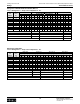
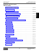

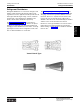
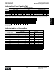
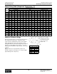

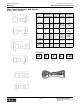
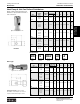
Table Of Contents
- MASTER TABLE of CONTENTS 1
- MASTER TABLE of CONTENTS 2ents 2
- CONTACT INFORMATION
- Cover
- Warning
- Your Preferred Supplier
- Value Added Services
- Value Added Parker Plus
- Residential AC Application
- Industrial Refrigeration Application
- Walk In Cooler Application
- Ice Machine Application
- Supermarket Application
- PHConnect
- EDI - Electronic Data Interchange
- Filter Dryer TOC
- Dryer Introduction
- Loose Filled Copper Dryers
- Loose Filled Spring Loaded Copper Dryers
- Service Copper Dryers
- Solid Core Copper Dryers
- Bi-Flow Copper Dryers
- Gold Label Steel Liquid Line Dryers
- Sahara Series Steel Liquid Line Dryers
- R410A Dryers
- BiFlow Stel Filter Dryers
- Gold Label Steel Suction Line Dryers
- Sahara Series Suction Line Dryers
- Dryer Shells and Cores
- Filter/Strainer/Oil Device TOC
- Accumulator, Receivers, Muffler TOC
- Sight Glass Moisture Indicator TOC
- Coupling TOC
- Service & Check Valve TOC
- TXV & AXV TOC
- Visual TOC 1
- Visual TOC 2
- S Series TXV
- I Series TXV
- EG Series TXV
- EGC Series TXV
- RE Series TXV
- H & HC Series TXV
- EC Series TXV
- ECC Series TXV
- G Series TXV
- N Series TXV
- C Series TXV
- B5 Series TXV
- PT Chart
- TXV Capacity Tables
- General TXV Information
- Valve Selection Procedure
- 104A & 104F Constant Pressure (AXV) Valves
- A Series Constant Pressure Valve (AXV)
- Model 139 Evaporator Pressure Regulator
- General Constant Pressure (AXV) Valve Information
- Model 625 Thermal Electric Valve
- Distributor & Flow Control TOC
- Refrigeration Solenoid Valves TOC
- R Series Refrigeration Solenoid Valves
- Introduction to Solenoid Valves
- Nomenclature
- General Specifications
- Ratings Summary
- R10 & R15 Series Solenoid Valves
- R20 & R25 Series Solenoid Valves
- R30 & R35 Solenoid Valves
- R40 & R45 Series Solenoid Valves
- R50 & R55 Series Solenoid Valves
- Electrical Specifications
- Coil Enclosures
- Capacity Tables
- Operating Principles
- Design Terminology
- Identification
- Agency Approvals
- Typical Applications
- 3-Way Hot Gas Defrost Valves
- Pulse Width Modulating Valves
- Secondary Coolant Solenoid Valves
- CROSS REFERENCE - R Series/Jackes Evans RB ORB
- Jackes Evans (RB/ORB Series)
- R Series Refrigeration Solenoid Valves
- General Purpose Solenoid Valves TOC
- FLO-CON Regulator & Valve TOC
- Overview
- (S)PORT & (S)PORT II Evaporator Pressure Regulators
- A8 Pressure Regulators
- A9 Pressure Regulators
- Suction Capacities A8, SPORT & SC
- A9 & A8 Condenser Bypass Capacities
- CK4 Check Valve
- Condenser Pressure Control
- Hot Gas Bypass
- Discharge Regulators for Supermarkets
- Crankcase Pressure Regulators
- SC Suction Solenoid Valves
- S81/S82 Solenoid Valves
- Abbreviations/Terminology
- Industrial Refrigeration TOC
- Warning/How to Use
- Pressure Regulators
- A2 Compact Regulators
- A2CK Relief Regulators
- A4 Adaptomode Regulators
- Weld End Regulators
- A2D Modular Presure Pilot
- S6A Modular Solenoid Pilot
- S6B Compact Modular Solenoid Pilot
- Modudapter
- Moduplate
- Vacuum Cartridge
- Outlet Regulator Kit
- Pressure Bonnet Kit
- Temperature Bonnet Kit
- Motor Bonnet Kit
- Electric Proportioning Thermostat
- Well, Separable
- Defrost Timer
- Handwheel
- Flange Ring-Tube Kits
- Class B Coil - S6A
- Class H Coil - S6B
- Voltages
- Solenoid Valves
- Gas Powered Suction Stop Valves
- Check Valves
- Safety Relief Valves
- Hand Valves
- Liquid Flow Regulators
- Refrigerant Float Switch
- Rapid Purger
- Automatic Liquid Drainer (ALD)
- Programmable Liquid Level Controller (PLLC)
- Flanges
- RS Strainers
- Liquid Drain Ball Valves
- Unibody Gauge Valves
- Gauges
- Depth Tracker Transducer Probes
- Open Refrigerant Pumps
- Hermetic Refrigerant Pumps
- Paint
- Warranties/Safe Operation
- Pressure in PSIG
- Pressure in Bar
- Offer of Sale
- Parker Hannifin Corporation
- Back Cover -CONTACT INFORMATION

Parker Hannifin Corporation
Climate & Industrial Controls Group
Cleveland, OH
Catalog CIC-2003-1/US
Distributors and Flow Controls
194
Technical Information Nozzle Type Refrigerant Distributors
Nozzle Type Distributors
Parker nozzle type distributors depend on the high
pressure drop through the orifice and the resulting
turbulence to provide equal distribution to all circuits.
The illustration below shows that the approaching
refrigerant streamlines nearest the pipe wall (W), then it
turns radial at the face of the nozzle towards the orifice.
This radial flow continues past the edge of the orifice
(X) and is moved through the orifice by the center mass
of the refrigerant. The refrigerant flow continues
through the orifice with a minimum jet area (Y) forming
past the nozzle. The uncontrolled expansion in the area
just past the nozzle causes a turbulent pattern (Z) to be
set-up between the jet area (Y) and the walls, which
dissipates the velocity energy. UL Listing 11550.
Look at the nozzle sizing table on page 196. Locate the
refrigerant that is being used across the top of the
table. Locate the temperature of the evaporator coil
under the desired refrigerant and go down the column
to the capacity of the coil. The required nozzle size is
in the first column of the table to the left of the coil
capacity.
Specifying the Distributor Body
To calculate the correct orifice size the following
information is needed:
1) the refrigerant type being used
2) number of circuits in the evaporator coil
3) the temperature of the evaporator coil
4) the capacity of the evaporator coil
Calculating the Circuit Size Tube
After gathering the above information, first calculate the
circuit capacity by dividing the evaporator coil capacity
by the number of circuits in the evaporator coil.
Next calculate the circuit tube size by using the
Distributor Tube Circuit Capacities Table on page 195.
Find the columns that are headed by the refrigerant
that is being used. Under the correct refrigerant header
are columns of evaporator column temperatures. Go
down the correct temperature column to the circuit ca-
pacity previously calculated then go the last column on
the left to find the circuit tube size.
Calculating the Body Type
Using the charts on pages 197-199 locate the column
titled "Maximum No. of Circuits" and go down the col-
umn until the required circuit diameter and the required
number of circuits are found. The body number is in the
first column. Look across the row to find the largest
"Nozzle" orifice for that body to ensure that the body
can support the required orifice. There may be a variety
of combinations that will work depending on the inlet
O.D. required. There is also a variety of inlet adapters
available such as added copper tubes with 1/2" or 5/8"
45 degree flare nuts, expanded ends, or straight ends
depending on the body selected.
Flow through a nozzle device.
No pressure recovery, high pressure drop.
Sizing Guidelines
Calculating the Orifice Size Needed
To calculate the correct orifice size needed the
refrigerant that is being used, the temperature of the
evaporator coil, and the capacity of the coil will need
to be known.