
Brochure
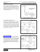
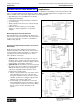

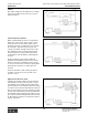
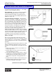

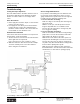

Table Of Contents
- MASTER TABLE of CONTENTS 1
- MASTER TABLE of CONTENTS 2ents 2
- CONTACT INFORMATION
- Cover
- Warning
- Your Preferred Supplier
- Value Added Services
- Value Added Parker Plus
- Residential AC Application
- Industrial Refrigeration Application
- Walk In Cooler Application
- Ice Machine Application
- Supermarket Application
- PHConnect
- EDI - Electronic Data Interchange
- Filter Dryer TOC
- Dryer Introduction
- Loose Filled Copper Dryers
- Loose Filled Spring Loaded Copper Dryers
- Service Copper Dryers
- Solid Core Copper Dryers
- Bi-Flow Copper Dryers
- Gold Label Steel Liquid Line Dryers
- Sahara Series Steel Liquid Line Dryers
- R410A Dryers
- BiFlow Stel Filter Dryers
- Gold Label Steel Suction Line Dryers
- Sahara Series Suction Line Dryers
- Dryer Shells and Cores
- Filter/Strainer/Oil Device TOC
- Accumulator, Receivers, Muffler TOC
- Sight Glass Moisture Indicator TOC
- Coupling TOC
- Service & Check Valve TOC
- TXV & AXV TOC
- Visual TOC 1
- Visual TOC 2
- S Series TXV
- I Series TXV
- EG Series TXV
- EGC Series TXV
- RE Series TXV
- H & HC Series TXV
- EC Series TXV
- ECC Series TXV
- G Series TXV
- N Series TXV
- C Series TXV
- B5 Series TXV
- PT Chart
- TXV Capacity Tables
- General TXV Information
- Valve Selection Procedure
- 104A & 104F Constant Pressure (AXV) Valves
- A Series Constant Pressure Valve (AXV)
- Model 139 Evaporator Pressure Regulator
- General Constant Pressure (AXV) Valve Information
- Model 625 Thermal Electric Valve
- Distributor & Flow Control TOC
- Refrigeration Solenoid Valves TOC
- R Series Refrigeration Solenoid Valves
- Introduction to Solenoid Valves
- Nomenclature
- General Specifications
- Ratings Summary
- R10 & R15 Series Solenoid Valves
- R20 & R25 Series Solenoid Valves
- R30 & R35 Solenoid Valves
- R40 & R45 Series Solenoid Valves
- R50 & R55 Series Solenoid Valves
- Electrical Specifications
- Coil Enclosures
- Capacity Tables
- Operating Principles
- Design Terminology
- Identification
- Agency Approvals
- Typical Applications
- 3-Way Hot Gas Defrost Valves
- Pulse Width Modulating Valves
- Secondary Coolant Solenoid Valves
- CROSS REFERENCE - R Series/Jackes Evans RB ORB
- Jackes Evans (RB/ORB Series)
- R Series Refrigeration Solenoid Valves
- General Purpose Solenoid Valves TOC
- FLO-CON Regulator & Valve TOC
- Overview
- (S)PORT & (S)PORT II Evaporator Pressure Regulators
- A8 Pressure Regulators
- A9 Pressure Regulators
- Suction Capacities A8, SPORT & SC
- A9 & A8 Condenser Bypass Capacities
- CK4 Check Valve
- Condenser Pressure Control
- Hot Gas Bypass
- Discharge Regulators for Supermarkets
- Crankcase Pressure Regulators
- SC Suction Solenoid Valves
- S81/S82 Solenoid Valves
- Abbreviations/Terminology
- Industrial Refrigeration TOC
- Warning/How to Use
- Pressure Regulators
- A2 Compact Regulators
- A2CK Relief Regulators
- A4 Adaptomode Regulators
- Weld End Regulators
- A2D Modular Presure Pilot
- S6A Modular Solenoid Pilot
- S6B Compact Modular Solenoid Pilot
- Modudapter
- Moduplate
- Vacuum Cartridge
- Outlet Regulator Kit
- Pressure Bonnet Kit
- Temperature Bonnet Kit
- Motor Bonnet Kit
- Electric Proportioning Thermostat
- Well, Separable
- Defrost Timer
- Handwheel
- Flange Ring-Tube Kits
- Class B Coil - S6A
- Class H Coil - S6B
- Voltages
- Solenoid Valves
- Gas Powered Suction Stop Valves
- Check Valves
- Safety Relief Valves
- Hand Valves
- Liquid Flow Regulators
- Refrigerant Float Switch
- Rapid Purger
- Automatic Liquid Drainer (ALD)
- Programmable Liquid Level Controller (PLLC)
- Flanges
- RS Strainers
- Liquid Drain Ball Valves
- Unibody Gauge Valves
- Gauges
- Depth Tracker Transducer Probes
- Open Refrigerant Pumps
- Hermetic Refrigerant Pumps
- Paint
- Warranties/Safe Operation
- Pressure in PSIG
- Pressure in Bar
- Offer of Sale
- Parker Hannifin Corporation
- Back Cover -CONTACT INFORMATION

Catalog CIC-2003-1/US
Parker Hannifin Corporation
Climate & Industrial Controls Group
Cleveland, OH
187
Service
& Check
Valves
Thermostatic and Constant Pressure (Automatic) Expansion Valves
TXVs & AXVs
Thermal Electric ValvesInstallation Information
If the line is at some angle other than vertical, the
lower or gravity side is preferable (see the illustration
at the right).
5. Thermistor location on horizontal suction lines is
more common and in some cases (large diameter
low velocity suction lines) permits adjustments to be
made in suction gas saturation (see illustration in
the right column). The best thermistor sensing
positions in horizontal suction lines are generally
between 4 o'clock and 8 o'clock in the lower half of
the suction line, although successful applications
have been made with the thermistor in all axial
locations. As a rule, the thermistor should be
located as high axially in the 4 to 8 o'clock range
as possible on horizontal suction lines using
tolerable suction gas wetness as the limiting
factor.
6. The most important rule regarding the location of
the liquid sensing thermistor on any applications is
simply this; make sure that liquid or wet refrigerant
gas can come into good contact with the thermistor
at all loads. Once a location has been established
on a given application, subsequent units will show
excellent repeatability.
Effects of Ambients and Blowers During Running
Periods – Exposure to fan or blower air movement has
almost no effect on the valve. It will operate properly in
all ambients from -40°F (-40°C) to +150°F (+66°C).
The valve has a normal tendency to lose capacity at
lower ambients and gain capacity at high ambients.
The thermistor, however, generally compensates for
these changes automatically.
Effect of Ambient During Off-Cycle Periods – During
off-cycle periods, the valve will bleed off refrigerant if
exposed to ambients above 70°F (21°C) and will close
off relatively tight if exposed to ambients of less than
70°F. In short, the valve is simply calibrated to close at
70°F with no electrical energy applied.
Off-Cycle System Unloading – The valve can be left
energized 100% of the time, in which case it will com-
pletely and rapidly unload the system during off-cycle
periods.
The valve can be de-energized during off-cycle periods
with the compressor, in which case it will partially
unload the system, depending upon the amount of
charge and the ambient. (See Effect of Ambient
During Off-Cycle Periods above).
Best Thermistor Sensing Positions on Horizontal
Suction Lines
Preferable Location for Thermistor Assembly on
Angled Line
Note: Do not install in vertical lines.