
Brochure
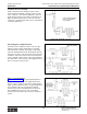
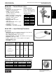
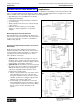

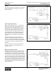
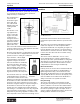
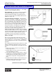

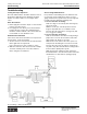

Table Of Contents
- MASTER TABLE of CONTENTS 1
- MASTER TABLE of CONTENTS 2ents 2
- CONTACT INFORMATION
- Cover
- Warning
- Your Preferred Supplier
- Value Added Services
- Value Added Parker Plus
- Residential AC Application
- Industrial Refrigeration Application
- Walk In Cooler Application
- Ice Machine Application
- Supermarket Application
- PHConnect
- EDI - Electronic Data Interchange
- Filter Dryer TOC
- Dryer Introduction
- Loose Filled Copper Dryers
- Loose Filled Spring Loaded Copper Dryers
- Service Copper Dryers
- Solid Core Copper Dryers
- Bi-Flow Copper Dryers
- Gold Label Steel Liquid Line Dryers
- Sahara Series Steel Liquid Line Dryers
- R410A Dryers
- BiFlow Stel Filter Dryers
- Gold Label Steel Suction Line Dryers
- Sahara Series Suction Line Dryers
- Dryer Shells and Cores
- Filter/Strainer/Oil Device TOC
- Accumulator, Receivers, Muffler TOC
- Sight Glass Moisture Indicator TOC
- Coupling TOC
- Service & Check Valve TOC
- TXV & AXV TOC
- Visual TOC 1
- Visual TOC 2
- S Series TXV
- I Series TXV
- EG Series TXV
- EGC Series TXV
- RE Series TXV
- H & HC Series TXV
- EC Series TXV
- ECC Series TXV
- G Series TXV
- N Series TXV
- C Series TXV
- B5 Series TXV
- PT Chart
- TXV Capacity Tables
- General TXV Information
- Valve Selection Procedure
- 104A & 104F Constant Pressure (AXV) Valves
- A Series Constant Pressure Valve (AXV)
- Model 139 Evaporator Pressure Regulator
- General Constant Pressure (AXV) Valve Information
- Model 625 Thermal Electric Valve
- Distributor & Flow Control TOC
- Refrigeration Solenoid Valves TOC
- R Series Refrigeration Solenoid Valves
- Introduction to Solenoid Valves
- Nomenclature
- General Specifications
- Ratings Summary
- R10 & R15 Series Solenoid Valves
- R20 & R25 Series Solenoid Valves
- R30 & R35 Solenoid Valves
- R40 & R45 Series Solenoid Valves
- R50 & R55 Series Solenoid Valves
- Electrical Specifications
- Coil Enclosures
- Capacity Tables
- Operating Principles
- Design Terminology
- Identification
- Agency Approvals
- Typical Applications
- 3-Way Hot Gas Defrost Valves
- Pulse Width Modulating Valves
- Secondary Coolant Solenoid Valves
- CROSS REFERENCE - R Series/Jackes Evans RB ORB
- Jackes Evans (RB/ORB Series)
- R Series Refrigeration Solenoid Valves
- General Purpose Solenoid Valves TOC
- FLO-CON Regulator & Valve TOC
- Overview
- (S)PORT & (S)PORT II Evaporator Pressure Regulators
- A8 Pressure Regulators
- A9 Pressure Regulators
- Suction Capacities A8, SPORT & SC
- A9 & A8 Condenser Bypass Capacities
- CK4 Check Valve
- Condenser Pressure Control
- Hot Gas Bypass
- Discharge Regulators for Supermarkets
- Crankcase Pressure Regulators
- SC Suction Solenoid Valves
- S81/S82 Solenoid Valves
- Abbreviations/Terminology
- Industrial Refrigeration TOC
- Warning/How to Use
- Pressure Regulators
- A2 Compact Regulators
- A2CK Relief Regulators
- A4 Adaptomode Regulators
- Weld End Regulators
- A2D Modular Presure Pilot
- S6A Modular Solenoid Pilot
- S6B Compact Modular Solenoid Pilot
- Modudapter
- Moduplate
- Vacuum Cartridge
- Outlet Regulator Kit
- Pressure Bonnet Kit
- Temperature Bonnet Kit
- Motor Bonnet Kit
- Electric Proportioning Thermostat
- Well, Separable
- Defrost Timer
- Handwheel
- Flange Ring-Tube Kits
- Class B Coil - S6A
- Class H Coil - S6B
- Voltages
- Solenoid Valves
- Gas Powered Suction Stop Valves
- Check Valves
- Safety Relief Valves
- Hand Valves
- Liquid Flow Regulators
- Refrigerant Float Switch
- Rapid Purger
- Automatic Liquid Drainer (ALD)
- Programmable Liquid Level Controller (PLLC)
- Flanges
- RS Strainers
- Liquid Drain Ball Valves
- Unibody Gauge Valves
- Gauges
- Depth Tracker Transducer Probes
- Open Refrigerant Pumps
- Hermetic Refrigerant Pumps
- Paint
- Warranties/Safe Operation
- Pressure in PSIG
- Pressure in Bar
- Offer of Sale
- Parker Hannifin Corporation
- Back Cover -CONTACT INFORMATION

Parker Hannifin Corporation
Climate & Industrial Controls Group
Cleveland, OH
Catalog CIC-2003-1/US
Thermostatic and Constant Pressure (Automatic) Expansion Valves
186
Thermal Electric ValvesInstallation Information
Mounting Position – The valve should be installed
such that the thermal head is within 30° of an upright
position to insure maximum capacity.
Sweat Soldering – The same precautions should be
used when sweating this valve into a system that
would normally be used with conventional valves to
prevent excessive temperature build up (damp cloth –
chill block – and so on).
Thermistor Suction Line Adapter – The thermistor
should be located flush, or slightly less, with the inside
wall of the suction line. The 5/16" dimension shown in
the second illustration at the right will correctly locate
the thermistor assembly with the inside wall of the suc-
tion line. Projection of the female adapter fittings, as
well as the thermistor assembly, into the suction line
should be avoided (see the illustration at the right).
Thermistor Location & Sensing Positions – The
liquid sensing thermistor assembly can be used in any
suction line with a diameter of 1/2" or larger. It will work
on both vertical and horizontal suction lines, but should
never be located where liquid refrigerant is likely to
accumulate or trap off. For instance; in a bottom U-
Bend connecting two vertical risers (see the bottom
graphic at the right).
Since suction refrigerant flow depends upon many
factors including suction line size, suction gas velocity,
elbows, reducers, etc.; it is important to establish firm
rules regarding the best location of the liquid sensing
thermistor.
The following observations have been made on a wide
variety of applications and have proven to be useful
guidelines for locating thermistor assemblies in suction
lines.
1. High velocity suction locations are preferable over
low velocity locations.
2. Smaller diameter suction locations are preferable
over larger diameter locations.
3. Unless the flow pattern around an elbow or reducer
is well known or specifically designed for the liquid
sensing thermistor assembly, it is best to stay at
least 6 inches away when locating downstream of
them.
4. Vertical suction lines make excellent locations, but
trapping should be avoided as mentioned earlier
(see the bottom graphic at the right).
(Continued on the following page.)
Thermal Electric Valve Model 625 Installation
Correct Placement of Thermistor Assembly into Suction
Line
Suction Line Identifying Location of Thermistor
Assembly
Note: Use refrigerant
compatible pipe sealant
on threads. Do not apply
sealant to end of
thermistor.
Correct and Incorrect Locations for Thermistor
Assembly
Incorrect location
Correct locations