
Brochure

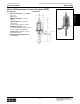
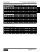
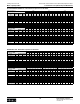

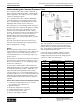
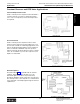
Table Of Contents
- MASTER TABLE of CONTENTS 1
- MASTER TABLE of CONTENTS 2ents 2
- CONTACT INFORMATION
- Cover
- Warning
- Your Preferred Supplier
- Value Added Services
- Value Added Parker Plus
- Residential AC Application
- Industrial Refrigeration Application
- Walk In Cooler Application
- Ice Machine Application
- Supermarket Application
- PHConnect
- EDI - Electronic Data Interchange
- Filter Dryer TOC
- Dryer Introduction
- Loose Filled Copper Dryers
- Loose Filled Spring Loaded Copper Dryers
- Service Copper Dryers
- Solid Core Copper Dryers
- Bi-Flow Copper Dryers
- Gold Label Steel Liquid Line Dryers
- Sahara Series Steel Liquid Line Dryers
- R410A Dryers
- BiFlow Stel Filter Dryers
- Gold Label Steel Suction Line Dryers
- Sahara Series Suction Line Dryers
- Dryer Shells and Cores
- Filter/Strainer/Oil Device TOC
- Accumulator, Receivers, Muffler TOC
- Sight Glass Moisture Indicator TOC
- Coupling TOC
- Service & Check Valve TOC
- TXV & AXV TOC
- Visual TOC 1
- Visual TOC 2
- S Series TXV
- I Series TXV
- EG Series TXV
- EGC Series TXV
- RE Series TXV
- H & HC Series TXV
- EC Series TXV
- ECC Series TXV
- G Series TXV
- N Series TXV
- C Series TXV
- B5 Series TXV
- PT Chart
- TXV Capacity Tables
- General TXV Information
- Valve Selection Procedure
- 104A & 104F Constant Pressure (AXV) Valves
- A Series Constant Pressure Valve (AXV)
- Model 139 Evaporator Pressure Regulator
- General Constant Pressure (AXV) Valve Information
- Model 625 Thermal Electric Valve
- Distributor & Flow Control TOC
- Refrigeration Solenoid Valves TOC
- R Series Refrigeration Solenoid Valves
- Introduction to Solenoid Valves
- Nomenclature
- General Specifications
- Ratings Summary
- R10 & R15 Series Solenoid Valves
- R20 & R25 Series Solenoid Valves
- R30 & R35 Solenoid Valves
- R40 & R45 Series Solenoid Valves
- R50 & R55 Series Solenoid Valves
- Electrical Specifications
- Coil Enclosures
- Capacity Tables
- Operating Principles
- Design Terminology
- Identification
- Agency Approvals
- Typical Applications
- 3-Way Hot Gas Defrost Valves
- Pulse Width Modulating Valves
- Secondary Coolant Solenoid Valves
- CROSS REFERENCE - R Series/Jackes Evans RB ORB
- Jackes Evans (RB/ORB Series)
- R Series Refrigeration Solenoid Valves
- General Purpose Solenoid Valves TOC
- FLO-CON Regulator & Valve TOC
- Overview
- (S)PORT & (S)PORT II Evaporator Pressure Regulators
- A8 Pressure Regulators
- A9 Pressure Regulators
- Suction Capacities A8, SPORT & SC
- A9 & A8 Condenser Bypass Capacities
- CK4 Check Valve
- Condenser Pressure Control
- Hot Gas Bypass
- Discharge Regulators for Supermarkets
- Crankcase Pressure Regulators
- SC Suction Solenoid Valves
- S81/S82 Solenoid Valves
- Abbreviations/Terminology
- Industrial Refrigeration TOC
- Warning/How to Use
- Pressure Regulators
- A2 Compact Regulators
- A2CK Relief Regulators
- A4 Adaptomode Regulators
- Weld End Regulators
- A2D Modular Presure Pilot
- S6A Modular Solenoid Pilot
- S6B Compact Modular Solenoid Pilot
- Modudapter
- Moduplate
- Vacuum Cartridge
- Outlet Regulator Kit
- Pressure Bonnet Kit
- Temperature Bonnet Kit
- Motor Bonnet Kit
- Electric Proportioning Thermostat
- Well, Separable
- Defrost Timer
- Handwheel
- Flange Ring-Tube Kits
- Class B Coil - S6A
- Class H Coil - S6B
- Voltages
- Solenoid Valves
- Gas Powered Suction Stop Valves
- Check Valves
- Safety Relief Valves
- Hand Valves
- Liquid Flow Regulators
- Refrigerant Float Switch
- Rapid Purger
- Automatic Liquid Drainer (ALD)
- Programmable Liquid Level Controller (PLLC)
- Flanges
- RS Strainers
- Liquid Drain Ball Valves
- Unibody Gauge Valves
- Gauges
- Depth Tracker Transducer Probes
- Open Refrigerant Pumps
- Hermetic Refrigerant Pumps
- Paint
- Warranties/Safe Operation
- Pressure in PSIG
- Pressure in Bar
- Offer of Sale
- Parker Hannifin Corporation
- Back Cover -CONTACT INFORMATION

Parker Hannifin Corporation
Climate & Industrial Controls Group
Cleveland, OH
Catalog CIC-2003-1/US
Thermostatic and Constant Pressure (Automatic) Expansion Valves
178
Constant Pressure (Automatic) and EPR ValvesTechnical Information
The constant pressure valve is a vital component of
many refrigeration and A/C systems. It automatically
meters refrigerant to the evaporator at a rate equal to
compressor pumping capacity.
The constant pressure valve contains a diaphragm,
control spring (FS1), seat and valve needle or ball.
The control spring, above the diaphragm, moves the
diaphragm down. This moves the valve open.
The opposing force is provided by low side evaporator
pressure (FE) and a constant body spring force (FS2).
This moves the valve closed. During the off cycle,
evaporator pressure builds and overcomes spring
pressure. This keeps the valve closed until the next on
cycle. At the start of the on cycle, the compressor
quickly reduces evaporator pressure. When this
pressure equals the control spring pressure, the valve
begins to open.
The valve opens when evaporator pressure is just
below the control spring pressure setting. This is the
valve’s opening point, or setting.
Bleeds
Bleed type valves permit pressures in the system to
reach a balance point during the off cycle. At the next
running cycle, the motor starts under practically no
load. This allows the use of low starting torque com-
pressor motors.
The bleed type (or slotted orifice) valve has a small slot
in the valve seat. This prevents complete close off at
the end of the machine’s-on cycle, permitting refriger-
ant flow at a reduced rate.
Proper selection should result in a bleed and orifice
which will always have control over the refrigerant flow
at all standard operating conditions. Application of a
larger bleed will speed equalization time, but may
cause the valve to lose control at high head pressure
operating conditions. Loss of control means all the flow
will be through the bleed and the valve will be closed
because the bleed capacity matches the compressor
capacity.
How to Select Constant Pressure Expansion Valves
1. Load on the system in Btu’s per hour or in tons
(12,000 Btu per hour equals 1 ton)
2. System refrigerant
3. Evaporator temperature or pressure
4. Condensing temperature or pressure
5. Pressure drop across the valve
6. Off-cycle unloading, if required
Elevation Change and Valve Setting
The control spring in a constant pressure valve works
with atmospheric pressure to move the valve in an
opening direction. Any substantial change in altitude
after a valve has been adjusted will alter the low side
flow rate maintained by the valve.
If a low side gauge is available, adjust the valve to
increase the system pressure above the sea level
reading by the amount shown in the gauge pressure
correction column of the table below.
Understanding the Constant Pressure Valve
Altitutde Gage Pressure
Feet Inches Hg. psia correction (psia)
0 29.92 14.70 -
500 29.38 14.70 -0.30
1000 28.86 14.19 -0.51
1500 28.33 13.91 -0.79
2000 27.82 13.58 -1.12
2500 27.32 13.41 -1.29
3000 26.82 13.20 -1.50
3500 26.33 12.92 -1.78
4000 25.84 12.70 -2.00
4500 25.37 12.44 -2.26
5000 24.90 12.23 -2.57
5500 24.43 12.01 -2.69
6000 23.98 11.78 -2.92
6500 23.53 11.55 -3.15
7000 23.09 11.33 -3.37
7500 22.65 11.10 -3.60
8000 22.22 10.92 -3.78
8500 21.80 10.70 -4.00
9000 21.39 10.50 -4.20
9500 20.98 10.30 -4.40
10000 120.58 10.10 -4.60
Barametric Pressure