
Brochure
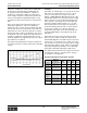

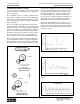

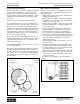
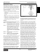
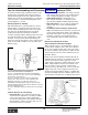
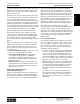
Table Of Contents
- MASTER TABLE of CONTENTS 1
- MASTER TABLE of CONTENTS 2ents 2
- CONTACT INFORMATION
- Cover
- Warning
- Your Preferred Supplier
- Value Added Services
- Value Added Parker Plus
- Residential AC Application
- Industrial Refrigeration Application
- Walk In Cooler Application
- Ice Machine Application
- Supermarket Application
- PHConnect
- EDI - Electronic Data Interchange
- Filter Dryer TOC
- Dryer Introduction
- Loose Filled Copper Dryers
- Loose Filled Spring Loaded Copper Dryers
- Service Copper Dryers
- Solid Core Copper Dryers
- Bi-Flow Copper Dryers
- Gold Label Steel Liquid Line Dryers
- Sahara Series Steel Liquid Line Dryers
- R410A Dryers
- BiFlow Stel Filter Dryers
- Gold Label Steel Suction Line Dryers
- Sahara Series Suction Line Dryers
- Dryer Shells and Cores
- Filter/Strainer/Oil Device TOC
- Accumulator, Receivers, Muffler TOC
- Sight Glass Moisture Indicator TOC
- Coupling TOC
- Service & Check Valve TOC
- TXV & AXV TOC
- Visual TOC 1
- Visual TOC 2
- S Series TXV
- I Series TXV
- EG Series TXV
- EGC Series TXV
- RE Series TXV
- H & HC Series TXV
- EC Series TXV
- ECC Series TXV
- G Series TXV
- N Series TXV
- C Series TXV
- B5 Series TXV
- PT Chart
- TXV Capacity Tables
- General TXV Information
- Valve Selection Procedure
- 104A & 104F Constant Pressure (AXV) Valves
- A Series Constant Pressure Valve (AXV)
- Model 139 Evaporator Pressure Regulator
- General Constant Pressure (AXV) Valve Information
- Model 625 Thermal Electric Valve
- Distributor & Flow Control TOC
- Refrigeration Solenoid Valves TOC
- R Series Refrigeration Solenoid Valves
- Introduction to Solenoid Valves
- Nomenclature
- General Specifications
- Ratings Summary
- R10 & R15 Series Solenoid Valves
- R20 & R25 Series Solenoid Valves
- R30 & R35 Solenoid Valves
- R40 & R45 Series Solenoid Valves
- R50 & R55 Series Solenoid Valves
- Electrical Specifications
- Coil Enclosures
- Capacity Tables
- Operating Principles
- Design Terminology
- Identification
- Agency Approvals
- Typical Applications
- 3-Way Hot Gas Defrost Valves
- Pulse Width Modulating Valves
- Secondary Coolant Solenoid Valves
- CROSS REFERENCE - R Series/Jackes Evans RB ORB
- Jackes Evans (RB/ORB Series)
- R Series Refrigeration Solenoid Valves
- General Purpose Solenoid Valves TOC
- FLO-CON Regulator & Valve TOC
- Overview
- (S)PORT & (S)PORT II Evaporator Pressure Regulators
- A8 Pressure Regulators
- A9 Pressure Regulators
- Suction Capacities A8, SPORT & SC
- A9 & A8 Condenser Bypass Capacities
- CK4 Check Valve
- Condenser Pressure Control
- Hot Gas Bypass
- Discharge Regulators for Supermarkets
- Crankcase Pressure Regulators
- SC Suction Solenoid Valves
- S81/S82 Solenoid Valves
- Abbreviations/Terminology
- Industrial Refrigeration TOC
- Warning/How to Use
- Pressure Regulators
- A2 Compact Regulators
- A2CK Relief Regulators
- A4 Adaptomode Regulators
- Weld End Regulators
- A2D Modular Presure Pilot
- S6A Modular Solenoid Pilot
- S6B Compact Modular Solenoid Pilot
- Modudapter
- Moduplate
- Vacuum Cartridge
- Outlet Regulator Kit
- Pressure Bonnet Kit
- Temperature Bonnet Kit
- Motor Bonnet Kit
- Electric Proportioning Thermostat
- Well, Separable
- Defrost Timer
- Handwheel
- Flange Ring-Tube Kits
- Class B Coil - S6A
- Class H Coil - S6B
- Voltages
- Solenoid Valves
- Gas Powered Suction Stop Valves
- Check Valves
- Safety Relief Valves
- Hand Valves
- Liquid Flow Regulators
- Refrigerant Float Switch
- Rapid Purger
- Automatic Liquid Drainer (ALD)
- Programmable Liquid Level Controller (PLLC)
- Flanges
- RS Strainers
- Liquid Drain Ball Valves
- Unibody Gauge Valves
- Gauges
- Depth Tracker Transducer Probes
- Open Refrigerant Pumps
- Hermetic Refrigerant Pumps
- Paint
- Warranties/Safe Operation
- Pressure in PSIG
- Pressure in Bar
- Offer of Sale
- Parker Hannifin Corporation
- Back Cover -CONTACT INFORMATION

Parker Hannifin Corporation
Climate & Industrial Controls Group
Cleveland, OH
Catalog CIC-2003-1/US
Thermostatic and Constant Pressure (Automatic) Expansion Valves
164
General Information Thermostatic Expansion Valves
Off Cycle Unloading (Bleed)
Internal bleed orifices are used to equalize the high and
low side pressures during the off cycle so that low
starting torque compressors can start. Systems such
as air conditioners and heat pumps sometimes require
a TXV with internal bleed due to the frequent cycling
that occurs.
Consult the factory if a bypass bleed is required.
The required bleed size is a function of high and low
side system volumes, refrigerant charge, and pressure
difference across the valve prior to shutdown. These
variables affect the equalization time required by a time
delay device or thermostat reset. Bleed sizes are usu-
ally specified as a percentage of the nominal valve ca-
pacity and can range from 5% to 50%, although 15% to
30% is more commonly specified.
At the end of the valve model number, a letter “B” fol-
lowed by digits indicates an internal bleed. These digits
represent the bleed capacity as a percentage of the
valve’s nominal capacity.
Example: SE5VX100B20 – Bleed orifice 20% of 5 tons,
or 1 ton bypass bleed.
Because the internal bleed is an additional flow path in
the valve, adding a bleed will increase the capacity of
the valve. Thus, a 5 ton valve with a 20% bleed is actu-
ally capable of 6 tons. However, intentionally adding an
internal bleed to increase the capacity of a valve is not
recommended.
Bulb Location and Installation
Since the control response of the bulb is crucial for sat-
isfactory operation, care should be taken in its mount-
ing and positioning.
• Always make sure the suction line is cleaned before
clamping the bulb in place.
• On lines that are 1/2" O.D. or smaller, the bulb may
be installed on top of the line or side mounted (pref-
erably at the 3 o’clock position).
• On lines that are 7/8" O.D. or larger, the remote bulb
should be installed at 45° or at approximately the 4
or 8 o’clock position.
• Never mount a bulb on the bottom of suction lines
because a mixture of refrigerant and oil may be
present at that point, especially on smaller lines.
• It is good practice to insulate the bulb regardless of
the refrigerant type. This ensures that the bulb will
only respond to the suction gas temperature and will
not be affected by condensation, ice formation or
ambient temperatures.
• Avoid mounting the bulb on vertical lines or close to
reversing valves.
• The bulb should always be mounted between the
evaporator outlet and the external equalizer connec-
tion and should be as close to the evaporator outlet
as possible (generally 3 to 6 inches).
• On systems that have multiple evaporators, the bulb
must be mounted on the suction line of the evapora-
tor which it controls. Do not mount the bulb on the
common suction line.
• Install traps on vertical risers. (See the illustration
below.)
1/2" & smaller
suction line
5/8" & larger
suction line
on smaller lines,
bulb may be mounted
on top
do not mount
bulb on bottom
of line
Installation of Traps