
Brochure

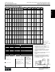
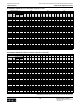
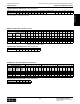
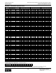
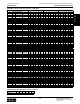

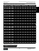

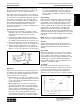
Table Of Contents
- MASTER TABLE of CONTENTS 1
- MASTER TABLE of CONTENTS 2ents 2
- CONTACT INFORMATION
- Cover
- Warning
- Your Preferred Supplier
- Value Added Services
- Value Added Parker Plus
- Residential AC Application
- Industrial Refrigeration Application
- Walk In Cooler Application
- Ice Machine Application
- Supermarket Application
- PHConnect
- EDI - Electronic Data Interchange
- Filter Dryer TOC
- Dryer Introduction
- Loose Filled Copper Dryers
- Loose Filled Spring Loaded Copper Dryers
- Service Copper Dryers
- Solid Core Copper Dryers
- Bi-Flow Copper Dryers
- Gold Label Steel Liquid Line Dryers
- Sahara Series Steel Liquid Line Dryers
- R410A Dryers
- BiFlow Stel Filter Dryers
- Gold Label Steel Suction Line Dryers
- Sahara Series Suction Line Dryers
- Dryer Shells and Cores
- Filter/Strainer/Oil Device TOC
- Accumulator, Receivers, Muffler TOC
- Sight Glass Moisture Indicator TOC
- Coupling TOC
- Service & Check Valve TOC
- TXV & AXV TOC
- Visual TOC 1
- Visual TOC 2
- S Series TXV
- I Series TXV
- EG Series TXV
- EGC Series TXV
- RE Series TXV
- H & HC Series TXV
- EC Series TXV
- ECC Series TXV
- G Series TXV
- N Series TXV
- C Series TXV
- B5 Series TXV
- PT Chart
- TXV Capacity Tables
- General TXV Information
- Valve Selection Procedure
- 104A & 104F Constant Pressure (AXV) Valves
- A Series Constant Pressure Valve (AXV)
- Model 139 Evaporator Pressure Regulator
- General Constant Pressure (AXV) Valve Information
- Model 625 Thermal Electric Valve
- Distributor & Flow Control TOC
- Refrigeration Solenoid Valves TOC
- R Series Refrigeration Solenoid Valves
- Introduction to Solenoid Valves
- Nomenclature
- General Specifications
- Ratings Summary
- R10 & R15 Series Solenoid Valves
- R20 & R25 Series Solenoid Valves
- R30 & R35 Solenoid Valves
- R40 & R45 Series Solenoid Valves
- R50 & R55 Series Solenoid Valves
- Electrical Specifications
- Coil Enclosures
- Capacity Tables
- Operating Principles
- Design Terminology
- Identification
- Agency Approvals
- Typical Applications
- 3-Way Hot Gas Defrost Valves
- Pulse Width Modulating Valves
- Secondary Coolant Solenoid Valves
- CROSS REFERENCE - R Series/Jackes Evans RB ORB
- Jackes Evans (RB/ORB Series)
- R Series Refrigeration Solenoid Valves
- General Purpose Solenoid Valves TOC
- FLO-CON Regulator & Valve TOC
- Overview
- (S)PORT & (S)PORT II Evaporator Pressure Regulators
- A8 Pressure Regulators
- A9 Pressure Regulators
- Suction Capacities A8, SPORT & SC
- A9 & A8 Condenser Bypass Capacities
- CK4 Check Valve
- Condenser Pressure Control
- Hot Gas Bypass
- Discharge Regulators for Supermarkets
- Crankcase Pressure Regulators
- SC Suction Solenoid Valves
- S81/S82 Solenoid Valves
- Abbreviations/Terminology
- Industrial Refrigeration TOC
- Warning/How to Use
- Pressure Regulators
- A2 Compact Regulators
- A2CK Relief Regulators
- A4 Adaptomode Regulators
- Weld End Regulators
- A2D Modular Presure Pilot
- S6A Modular Solenoid Pilot
- S6B Compact Modular Solenoid Pilot
- Modudapter
- Moduplate
- Vacuum Cartridge
- Outlet Regulator Kit
- Pressure Bonnet Kit
- Temperature Bonnet Kit
- Motor Bonnet Kit
- Electric Proportioning Thermostat
- Well, Separable
- Defrost Timer
- Handwheel
- Flange Ring-Tube Kits
- Class B Coil - S6A
- Class H Coil - S6B
- Voltages
- Solenoid Valves
- Gas Powered Suction Stop Valves
- Check Valves
- Safety Relief Valves
- Hand Valves
- Liquid Flow Regulators
- Refrigerant Float Switch
- Rapid Purger
- Automatic Liquid Drainer (ALD)
- Programmable Liquid Level Controller (PLLC)
- Flanges
- RS Strainers
- Liquid Drain Ball Valves
- Unibody Gauge Valves
- Gauges
- Depth Tracker Transducer Probes
- Open Refrigerant Pumps
- Hermetic Refrigerant Pumps
- Paint
- Warranties/Safe Operation
- Pressure in PSIG
- Pressure in Bar
- Offer of Sale
- Parker Hannifin Corporation
- Back Cover -CONTACT INFORMATION

Catalog CIC-2003-1/US
Parker Hannifin Corporation
Climate & Industrial Controls Group
Cleveland, OH
159
Service
& Check
Valves
Thermostatic and Constant Pressure (Automatic) Expansion Valves
TXVs & AXVs
General Information Thermostatic Expansion Valves
valve will stroke in the closing direction in response to
the reduced heat load on the evaporator, again main-
taining the proper evaporator outlet superheat.
The superheated suction gas flows to the compressor
where its pressure and temperature are increased due
to compression. The superheated discharge gas from
the compressor then flows to the condenser where
heat isrejected, changing the gas into a high pressure
subcooled liquid. The liquid refrigerant then flows to
the expansion valve inlet and is metered into the
evaporator at a flow rate necessary to maintain proper
evaporator superheat.
How To Determine Superheat
1. Determine suction pressure at evaporator outlet
with gauge. On close coupled installations, suction
pressure may be read at compressor suction
connection.
2. Use Pressure-Temperature Chart to determine
saturation temperature at observed suction pressure.
For example, with an R-22 system: 54.9 psig = 30°F.
3. Measure temperature of suction gas at the expan-
sion valve’s remote bulb location. For example: 40°F.
4. Subtract saturation temperature of 30°F (Step 2)
from suction gas temperature of 40°F (Step 3). The
difference, 10°F, is the superheat of the suction gas.
Determining Superheat
Superheat
Superheat is the temperature of refrigerant gas above
its saturated vapor (dewpoint) temperature. Superheat
as it relates to thermostatic expansion valves, can be
broken down into three categories:
• Static Superheat – The amount of superheat neces-
sary to overcome the superheat spring force biased
in a closed position. Any additional superheat (force)
would open the valve.
• Opening Superheat – The amount of superheat
necessary to open the valve to its rated capacity.
• Operating Superheat – The superheat at which the
valve operates at normal running conditions or
normal capacity. The operating superheat is the sum
of the static and opening superheat. The figure
at the right illustrates the three superheat catego-
ries. The reserve capacity, as shown in the graph, is
important since it provides the ability to compensate
for occasional substantial increases in evaporator
load, intermittent flash gas, reduction in high side
pressure due to low ambient conditions, shortage of
refrigerant, etc.
Valve Setting
Parker “sets” the thermostatic expansion valve super-
heat at the static condition described above. Turning
the adjusting screw clockwise will increase the static
superheat. Conversely, turning the adjusting screw
counterclockwise will decrease the superheat. Parker
valves can also be adjusted at the operating point,
indicated above. When a system is operating, any
adjustments made will change the operating superheat.
The static superheat range of adjustment is 3°F to 18°F.
One full turn clockwise will typically increase superheat
2°F to 4°F.
NOTE: Refer to the valve’s installation bulletin for
specific directions on superheat adjustment.
Charges
Power elements may be system charged (charged
with the same refrigerant used in the system) or cross
charged (refrigerant different from that used in the
system).
“ W” Charge
The Parker “W” liquid cross charge can be used with
evaporator temperatures from -40°F to +60°F (-40°C to
+15°C). Unlike conventional cross charges, the “W”
charge maintains a nearly constant superheat through-
out this range of evaporator temperatures. A liquid
charged bulb maintains control even when the power
element is colder than the bulb.
“ Z” Charge
The Parker “Z” low temperature liquid cross charge
can be used with evaporator temperatures from -40°F
to 0°F (-40°C to -20°C). The “Z” cross charge is de-
signed specifically for low temperature applications;
therefore, it can control the system so that the desired
Superheat Capacities