
Brochure

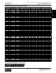

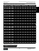

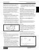
Table Of Contents
- MASTER TABLE of CONTENTS 1
- MASTER TABLE of CONTENTS 2ents 2
- CONTACT INFORMATION
- Cover
- Warning
- Your Preferred Supplier
- Value Added Services
- Value Added Parker Plus
- Residential AC Application
- Industrial Refrigeration Application
- Walk In Cooler Application
- Ice Machine Application
- Supermarket Application
- PHConnect
- EDI - Electronic Data Interchange
- Filter Dryer TOC
- Dryer Introduction
- Loose Filled Copper Dryers
- Loose Filled Spring Loaded Copper Dryers
- Service Copper Dryers
- Solid Core Copper Dryers
- Bi-Flow Copper Dryers
- Gold Label Steel Liquid Line Dryers
- Sahara Series Steel Liquid Line Dryers
- R410A Dryers
- BiFlow Stel Filter Dryers
- Gold Label Steel Suction Line Dryers
- Sahara Series Suction Line Dryers
- Dryer Shells and Cores
- Filter/Strainer/Oil Device TOC
- Accumulator, Receivers, Muffler TOC
- Sight Glass Moisture Indicator TOC
- Coupling TOC
- Service & Check Valve TOC
- TXV & AXV TOC
- Visual TOC 1
- Visual TOC 2
- S Series TXV
- I Series TXV
- EG Series TXV
- EGC Series TXV
- RE Series TXV
- H & HC Series TXV
- EC Series TXV
- ECC Series TXV
- G Series TXV
- N Series TXV
- C Series TXV
- B5 Series TXV
- PT Chart
- TXV Capacity Tables
- General TXV Information
- Valve Selection Procedure
- 104A & 104F Constant Pressure (AXV) Valves
- A Series Constant Pressure Valve (AXV)
- Model 139 Evaporator Pressure Regulator
- General Constant Pressure (AXV) Valve Information
- Model 625 Thermal Electric Valve
- Distributor & Flow Control TOC
- Refrigeration Solenoid Valves TOC
- R Series Refrigeration Solenoid Valves
- Introduction to Solenoid Valves
- Nomenclature
- General Specifications
- Ratings Summary
- R10 & R15 Series Solenoid Valves
- R20 & R25 Series Solenoid Valves
- R30 & R35 Solenoid Valves
- R40 & R45 Series Solenoid Valves
- R50 & R55 Series Solenoid Valves
- Electrical Specifications
- Coil Enclosures
- Capacity Tables
- Operating Principles
- Design Terminology
- Identification
- Agency Approvals
- Typical Applications
- 3-Way Hot Gas Defrost Valves
- Pulse Width Modulating Valves
- Secondary Coolant Solenoid Valves
- CROSS REFERENCE - R Series/Jackes Evans RB ORB
- Jackes Evans (RB/ORB Series)
- R Series Refrigeration Solenoid Valves
- General Purpose Solenoid Valves TOC
- FLO-CON Regulator & Valve TOC
- Overview
- (S)PORT & (S)PORT II Evaporator Pressure Regulators
- A8 Pressure Regulators
- A9 Pressure Regulators
- Suction Capacities A8, SPORT & SC
- A9 & A8 Condenser Bypass Capacities
- CK4 Check Valve
- Condenser Pressure Control
- Hot Gas Bypass
- Discharge Regulators for Supermarkets
- Crankcase Pressure Regulators
- SC Suction Solenoid Valves
- S81/S82 Solenoid Valves
- Abbreviations/Terminology
- Industrial Refrigeration TOC
- Warning/How to Use
- Pressure Regulators
- A2 Compact Regulators
- A2CK Relief Regulators
- A4 Adaptomode Regulators
- Weld End Regulators
- A2D Modular Presure Pilot
- S6A Modular Solenoid Pilot
- S6B Compact Modular Solenoid Pilot
- Modudapter
- Moduplate
- Vacuum Cartridge
- Outlet Regulator Kit
- Pressure Bonnet Kit
- Temperature Bonnet Kit
- Motor Bonnet Kit
- Electric Proportioning Thermostat
- Well, Separable
- Defrost Timer
- Handwheel
- Flange Ring-Tube Kits
- Class B Coil - S6A
- Class H Coil - S6B
- Voltages
- Solenoid Valves
- Gas Powered Suction Stop Valves
- Check Valves
- Safety Relief Valves
- Hand Valves
- Liquid Flow Regulators
- Refrigerant Float Switch
- Rapid Purger
- Automatic Liquid Drainer (ALD)
- Programmable Liquid Level Controller (PLLC)
- Flanges
- RS Strainers
- Liquid Drain Ball Valves
- Unibody Gauge Valves
- Gauges
- Depth Tracker Transducer Probes
- Open Refrigerant Pumps
- Hermetic Refrigerant Pumps
- Paint
- Warranties/Safe Operation
- Pressure in PSIG
- Pressure in Bar
- Offer of Sale
- Parker Hannifin Corporation
- Back Cover -CONTACT INFORMATION

Parker Hannifin Corporation
Climate & Industrial Controls Group
Cleveland, OH
Catalog CIC-2003-1/US
158
Thermostatic and Constant Pressure (Automatic) Expansion Valves
Applications and General Information Thermostatic Expansion Valves
Applications
Bi-Directional Valves
The conventional means of applying thermostatic
expansion valves to a split system heat pump is shown
in the schematic below. This system employs two ther-
mostatic expansion valves and two check valves and
could be simplified by using a single thermostatic ex-
pansion valve as depicted in the schematic at the right
labelled “Bi-directional TXV.”
The drawing at the bottom right is a schematic of a
heat pump employing a single externally equalized
bi-directional thermostatic expansion valve controlling
superheat in both the cooling and heating modes. The
balanced port valve is ideally suited for this application
since its internal construction prevents liquid by-pass
through the external equalizer connection in both
Thermostatic Expansion Valve
modes of operation.
Only externally equalized
valves
can be used for this application.
When the bi-directional valve is used on a split system
and installed on the condensing unit, it may be neces-
sary to insulate the tubing between the expansion valve
and the indoor heat exchanger. To decrease the
pressure drop, it may also be necessary to increase
the diameter of the insulated tubing. These system
modifications are not necessary when the valve is
applied to a single packaged heat pump.
Note: The schematics at the right show the air condi-
tioning systems in the cooling mode. By switching the
4-way valve, flow from the compressor will be directed
from the outdoor coil to the indoor coil changing the
systems from cooling to heating.
Conventional TXV
Bi-directional TXV
Use models HC, EGC, ECC
General Information
Operation
The thermostatic expansion valve is a metering device
designed to regulate the flow of liquid to the vaporator,
at a rate equal to the evaporation of the liquid in the
evaporator. This is accomplished by maintaining a
predetermined superheat at the evaporator outlet
(suctionline) which ensures that all liquid refrigerant
vaporizes in the evaporator with only refrigerant gas
returning to thecompressor.
The thermostatic expansion valve (see the schematic
at the right) is installed in the liquid line at the evapora-
tor inlet separating the high and low pressure side of
the system. The thermal bulb is connected to the outlet
of the evaporator, sensing the evaporator outlet
temperature. The expansion valve will remain in the
closed position until the preset superheat setting is
reached. Subsequently, refrigerant flow through the
valve orifice will maintain a flow rate consistent with
the heat load and the valve superheat setting. If the
temperature sensed by the thermal bulb increases, the
flow rate will increase, maintaining the proper evapora-
tor outlet superheat. If the temperature decreases, the