
User's Manual


M7X and M7R Page 5-10 Maintenance
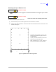
Back to Menu
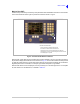
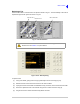
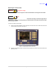
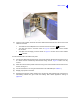
Fig 5-5 BIT Monitor Screen
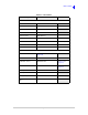
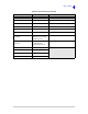
Table 5-2 BIT Parameters
Parameter Monitoring Range Remedial Reference
Processor module OK or Fault
See Replacing the Processor Module on
page 22.
RF control module OK or Fault
See Replacing the RF Control Module on
page 24.
RF PA module OK or Fault See Replacing the RF PA on page 27.
PSU module OK or Fault See Replacing the PSU Module on page 33.
Control head module OK or Fault or N/A See Replacing the Control Head on page 15.
Interface module OK or Fault
See Replacing the Interface Module on
page 26.
Guard receiver module OK or Fault or N/A
See Replacing the Guard Receiver Module on
page 21.
Custom interface module OK, Fault or N/A
See Replacing the Custom Interface Module
on page 20.
Main chassis fan OK or Fault
See Replacing a Fan on page 13.Heatsink fan 1 OK or Fault
Heatsink fan 2 OK or Fault
Receive RF cable OK or Fault
See Replacing Faulty Cables on page 38.
In this figure, Processor Module is highlighted; this is BIT Monitored Parameters 1 of 28 in the List. The Up
and Down keys allow scrolling through all BIT Monitored Parameters.
The number of BIT parameters that are monitored depends on the radio type, and the options that are fitted.
The number 28 shown in this figure, is an example.