
User's Manual

M7X and M7R Page 5-21 Maintenance
Back to Menu
Replacing the Guard Receiver Module
Ensure the input ac and dc supplies to the radio are disconnected before removing the top
cover.
Do not remove the radio’s top cover for at least one minute after switching off the radio.
This equipment contains devices sensitive to electrostatic discharge. Precautions applicable
to handling such equipment, including wearing a static protection wrist strap connected to
earth, should always be taken.
To replace the Guard Receiver module:
(1) Remove the radio’s top cover as detailed on
page 5-12.
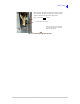
(2) Refer to
Fig 5-14 on page 5-18 and identify the Guard Receiver module’s position (Module C).
(3) At the Guard Receiver module, disconnect CN6; this cable connects the module to the RF PA
connector CN7.
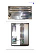
(4) Using a Torx T15 screwdriver, remove and retain the front and rear module securing screws
(
Fig 5-16 on page 5-19).
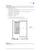
(5) Carefully lift the module disconnecting it from its socket (
Fig 5-15 on page 5-19).
(6) Place the replacement module in position and press down to ensure it is fully located in the
chassis socket.
(7) Fit and tighten the front and rear module securing screws (
Fig 5-16 on page 5-19).
(8) At the Guard Receiver, reconnect the cable at CN6.
(9) Refit the radio’s top cover (see
page 5-12).
(10) Connect the radio to a PC using the Lemo to USB cable.
(11) Re-apply input power to the radio.
(12) Download the Guard Receiver module software from the Park Air radio software CD. Instructions
for downloading software are given under the heading ‘Data Loader Application’ starting on
page 5-39.
WARNING Dangerous Voltage
WARNING Dangerous Voltage
Caution ESDs