
User's Manual

M7X and M7R Page 5-18 Maintenance
Back to Menu
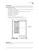
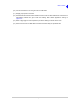
Plug-In Modules
The radio contains a number plug-in modules. These are listed below and are located as shown in
Fig 5-14. Note that after replacing any module, the build status requires amendment – see Data Loader
Application starting on
page 5-39.
Module position A – Not used
Module position B – Custom Interface module. This is an optional module used to accommodate
a user’s special interfacing requirement.
Module position C – Guard Receiver module. Optional VHF and UHF guard receiver
Module position D – Processor module
Module position E – RF Control module
Module position F – Interface module
Module position G – RF PA
Control head – fitted at radio’s front panel (see page 5-15)
PSU module – located on underside of radio below the RF PA position
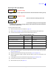
Fig 5-14 Module Layout
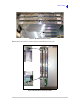
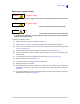
Modules B to F
Modules B to F each mate with a multi-way socket fitted on the chassis base. The module connection
sockets are shown in
Fig 5-15.
RC INTERFACE
CUSTOM INTERFACE
GUARD RECEIVER
RF CONTROL
PROCESSOR
STANDARD INTERFACE
Optional Custom Interface Module
Optional Guard Receiver Module
Processor Module
RF Control Module
Interface Module
RF PA Cover
G
Control Head
PSU Module on
the underside of radio
below RF PA
A B C D E F