
User's Manual


M7X and M7R Page 5-16 Maintenance
Back to Menu
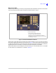
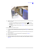
Fig 5-12 Replacing the Control Head (2)
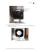
(3) From the Control Head, disconnect the three cables listed below and then remove the control
head from the radio.
The cable from the loudspeaker box connects to the Control Head’s connector
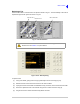
The cable from the E1 connector shown in Fig 5-13 connects to the Control Head’s
E1 connector
The cable from the Supply connector shown in Fig 5-13 connects to the Control Head’s
connector.
To fit the Control Head to the radios front panel:
(1) Connect the cables disconnected during control head removal. Should both ends of the DC or
E1 cables become inadvertently disconnected during removal,
Fig 5-13 shows how they
connect.
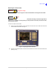
(2) Place the Control Head in position and secure using a Torx T20 screwdriver and four M4 x 6 mm
screws; see Fig 5-11.
(3) Connect the radio to a PC using the Control Head to PC USB cable (see
Table 5-1).
(4) Reapply input power to the radio.
(5) Download the Interface module software from the Park Air radio software CD. Instructions for
downloading software are given under the heading ‘Data Loader Application’ starting on
page 5-39.