
User's Manual


M7X and M7R Page 4-32 Installation
Back to Menu
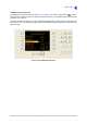
Ethernet Connector
An 8-way RJ48 socket marked Ethernet that is used to connect the radio to a 10/100Base-T ethernet
network.
The pin-out is listed in Table 4-19.
The connector has two integral indicators:
Green indicator. Lit indicates 100Base-T; unlit indicates 10Base-T.
Amber indicator. Lit indicates a valid link is detected; flashing to indicate link activity.
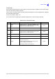
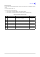
Table 4-19 Ethernet Connector Pin-Out
Pin Signal Characteristics Input or Output
1
2
TD +
TD -
Balanced 100 ohm, 10/100 Mbps. Output
3 RD + Balanced 100 ohm, 10/100 Mbps. Input
4 Not used Connected to 0 V (via 75 ohm and 1 nF). -
5 Not used Connected to 0 V (via 75 ohm and 1 nF). -
6 RD - Paired with pin 3. Input
7 Not used Connected to 0 V (via 75 ohm and 1 nF). -
8 Not used Connected to 0 V (via 75 ohm and 1 nF). -