
User's Manual


M7X and M7R Page 4-31 Installation
Back to Menu
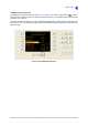
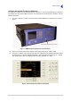
T1 Connector
An 8-way RJ48 socket marked T1 that is used to connect the radio to a digital voice and data network
such as a VDL Mode 3 network computer.
This connector can also be used to connect a split-site transmitter and receiver together when operating
as a VDL Mode 2 base station.
The pin-out is listed in Table 4-18.
The connector has an integral green indicator that lights when a valid T1 signal is detected.
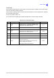
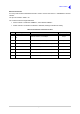
Table 4-18 T1 Connector Pin-Out
Pin Signal Characteristics Input or Output
1
2
RRing
RTip
Balanced 100 ohm, 1.544 Mbps, AMI/B8ZS coding.
Protected with 28 V differential and common mode
clamp and a 1.25 A fuse in each line.
Input
3 Not connected - -
4
5
TRing
TTip
Balanced 100 ohm, 1.544 Mbps, AMI/B8ZS coding.
Protected with 28 V differential and common mode
clamp and a 1.25 A fuse in each line.
Output
6 Not connected - -
7Ground 0 V. -
8 Supply
When the radio is operating from an ac input, the
output is 24 Vdc (±1 V).
When the radio is operating from a dc input, the
output is between 20 and 32 Vdc.
The Supply output is fused at 500 mA.
Output