
User's Manual

M7X and M7R Page 4-30 Installation
Back to Menu
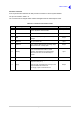
E1 Connector
An 8-way RJ48 socket marked E1 that is used to connect the radio to a digital voice and data network
such as a voice switch or remote controller.
The pin-out is listed in Table 4-17.
The connector has an integral green indicator that lights when a valid E1 signal is detected.
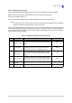
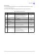
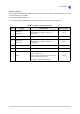
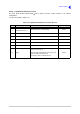
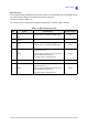
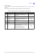
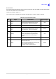
Table 4-17 E1 Connector Pin-Out
Pin Signal Characteristics Input or Output
1
2
RRing
RTip
Balanced 120 ohm, 2.048 Mbps, HDB3 coding.
Protected with 28 V differential and common
mode clamp and a 1.25 A fuse in each line.
Input
3 Not connected - -
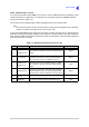
4
5
TRing
TTip
Balanced 120 ohm, 2.048 Mbps, HDB3 coding.
Protected with 28 V differential and common
mode clamp and a 1.25 A fuse in each line.
Output
6 Standby
0 V input to switch the radio to Standby mode. An
open circuit switches the radio to normal
operation. Note that the front panel Standby
switch must be set to On for this facility to
operate.
Input
7 Ground 0 V. -
8 Supply
When the radio is operating from an ac input, the
output is 24 Vdc (±1 V).
When the radio is operating from a dc input, the
output is between 20 and 32 Vdc.
The Supply output is fused at 500 mA.
Output