
User's Manual

M7X and M7R Page 4-17 Installation
Back to Menu
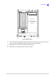
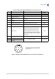
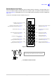
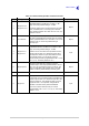
Fig 4-12 Microphone/Headset/Maintenance Connector Pin Arrangement
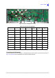
Table 4-6 Microphone/Headset/Maintenance Connector Pin-Out
Pin Signal Characteristic Input or
Output
1 Headset A+ (non-boom side) Adjustable between 0 and 3 V pk-pk Output
2 Headset A ground 0 V -
3 PTT 0 V to PTT Input
4Ground 0V -
5 Headset B+ (boom side) Adjustable between 0 and 3 V pk-pk Output
6 Headset B ground 0 V -
7 Microphone +
Between 2 and 35 mV rms on the High
sensitivity setting to remain in ALC range
Between 8 and 140 mV rms on the Low
sensitivity setting to remain in ALC range
Use Active setting for a powered microphone.
Use the Passive setting for a non-powered
microphone
Input
8 Microphone ground 0 V -
9 USB D-
-1 to +4.6 V differential voltage Input/Output
10 USB D+
1
2
3
4
5
6
7
8
9
10
This illustration shows the radio’s chassis
mounted connector as seen looking from the
front of the radio.