
User's Manual

M7X and M7R Page 4-11 Installation
Back to Menu
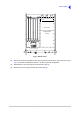
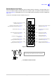
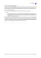
Fig 4-7 RF PA Cover
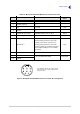
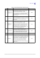
(4) Identify the antenna configuration links (Fig 4-8) that are located at the rear of the RF PA (see
Fig 4-7). Set links, as detailed in Table 4-5, to suit the required configuration.
(5) Refit the RF PA cover using the screws removed in step (3).
(6) Refit the top cover using the screws removed in step (2).
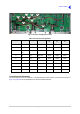
RC INTERFACE
CUSTOM INTERFACE
GUARD RECEIVER
RF CONTROL
PROCESSOR
STANDARD INTERFACE
RF PA Cover
ABCDEF
M3 x 6 mm countersunk
(26 off)
securing screws
Antenna configuration links
(see Fig 4-8) located under RF
PA cover.