
User's Manual

M7X and M7R Page 4-4 Installation
Back to Menu
Introduction
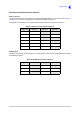
The procedures necessary to install an M7X or M7R are listed in Table 4-1.
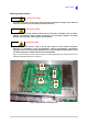
Initial Inspection of the Radio
On receipt of the radio, remove all transit packaging and check that there is no damage. If damage is
evident, contact Park Air immediately and retain the original transit packaging.
The following items are supplied with each radio.
CD containing the user documentation in interactive Adobe Acrobat format
Customer kit, part number 70-M7VUCUST, containing:
(1) dc input connector (female), part number 20S02040103 (Quantity 1)
(2) ac input lead complete with IEC connector, part number 17-03000038S (Quantity 1)
(3) RJ45 to RJ45 communication lead (pin-to-pin), part number 17H12000020 (Quantity 2)
(4) 10 amp anti-surge, 20 mm, ac input fuse, part number 29-01100102 (Quantity 2)
(5) 30 amp, 1¼ x ¼ inch, dc input fuse, part number 29-01460202 (Quantity 2).
CD containing the Park Air radio software as installed during manufacture.
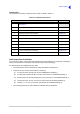
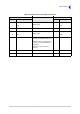
Table 4-1 Installation Procedures
Procedure Reference
1
Read and understand the warnings and cautions given on page 4-2
and page 4-3.
2 Perform an initial inspection of the radio. see page 4-4.
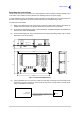
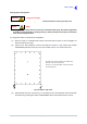
3 Fit the radio into an equipment cabinet (if required). see page 4-5.
4 Extend the Control Head if required. see page 4-7.
5 Select the required antenna option. see page 4-9.
4 Connect an antenna, or antennas, as required. see page 4-12.
5 Connect the chassis stud to the cabinet or system earth. see page 4-13.
6 Connect the dc input supply (if required). see page 4-14.
7 Connect the ac input supply (if required). see page 4-15.
8 Connect a microphone (if required) see page 4-16.
9 Make external signal connections as required. see page 4-18