
User's Guide


Page 17
Back to Transceiver
Main Page
Removing and Refitting the Power Supply
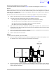
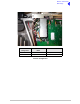
The Power Supply is located as shown in Fig 3. A module removal diagram is shown in Fig 7.
Removal
Before attempting to remove the Power Supply, ensure that the transceiver is isolated from the ac and
dc input supplies. Then proceed as follows:
(1) Remove the transceiver’s top and bottom covers as described on page 10 and page 14 (take
heed of the warnings on those pages).
(2) Support the radio on its side.
(3) Locate the power supply. From the bottom half of the unit remove the four No. 6 x 32 UNC
countersunk screws that secure the power supply to the transceiver’s mainframe. During this
operation support the power supply from the top half of the unit.
(4) Withdraw the power supply from the chassis sufficient to allow access to the power terminal
blocks taking care not to damage the ac terminal plastic supply guard.
(5) Remove the connector CN4 (power supply to the power regulator).
(6) Disconnect the dc wires from the eight connector terminal block.
(7) Slide back the terminal block cover and disconnect the ac wires from the three connector terminal
block (marked L N E).
(8) Carefully remove the power supply from the transceiver.
Refitting
(1) With the transceiver on its side hold the power supply near to its securing position in the top half
of the radio.
(2) Slide back the terminal block cover and connect the ac wires to the three connector terminal
block (marked L N E); brown to terminal L, blue to terminal N and yellow/green to terminal E.
(3) Connect the dc wires to the eight connector terminal block; red to terminal 2 and terminal 3 and
black to terminal 6 and terminal 7.
(4) Connect connector CN4.
(5) Taking care not to damage the plastic supply guard, lower the Power Supply into position and
secure from the bottom half of the unit using the four countersunk screws.
(6) Re-establish the ac and/or dc dc supplies (take heed of the warnings on page 10 and page 14).
(7) Switch power on at the radio using the rear mounted Power switch.
(8) Ensure the front panel Ready indicator is lit and the Alarm indicator is unlit.
(9) Carry out a BIT interruptive test as detailed in the procedure To Initiate a BIT Test on page 7.
(10) Switch power off at the transceiver using the rear mounted Power switch. Isolate the transceiver
from the ac and/or dc supplies.
(11) Refit the transceiver’s top and bottom covers (take note of Repairs caution (1) on page 5 before
carrying out this task). The transceiver can now be returned to service.