
User's Guide


Page 11
Back to Transceiver
Main Page
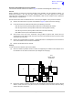
Removing and Refitting the Processor Module
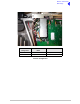
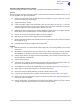
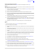
The Processor module is located as shown in Fig 3. A module removal diagram is shown in Fig 4.
Removal
Before attempting to remove the Processor module, and if possible, save the equipment settings. To
achieve this connect a PC, with the VFP software loaded, to the radio using the PC to Radio
Interconnection Lead (Park Air part number 17E12600001). With the VFP software active, upload the
radio settings to a specified file.
Ensure that the transceiver is isolated from the ac and dc input supplies. Then proceed as follows:
(1) Remove the transceiver’s top cover as described on page 10 (take heed of the warning).
(2) Locate the Processor module and disconnect the following connectors:
❑ CN1 50-way connector (50-way ribbon cable from PA Control/Rx RF module)
❑ CN3 14-way connector (14-way ribbon cable from PSU Regulator module)
❑ CN4 34-way connector (34-way ribbon cable from Front Panel module)
❑ CN2 SMB connector (to PA Control/Rx RF module).
(3) Gain access to the rear of the transceiver. Using a 6BA nut spinner tool, remove the four
screwloc 8 mm-4-40 UNC screws that secure the Processor module interface connectors CN5
and CN6 to the rear panel.
(4) Remove the 11 (Mod Strike 5 modules), 7 (Mod Strike 6 and 7 modules) M3 x 8 mm screws that
secure the module to the transceiver’s mainframe.
(5) Remove the module from the chassis.
Refitting
To refit the Processor module, proceed as follows:
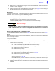
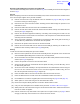
(1) Place the module in position. Ensure no wires are trapped by the module. Ensure jumper J2 on
the module is set to ‘R/TR’ for transceiver (see diagram on this page).
(1) Ensure the module’s interface connectors CN5 and CN6 are located correctly and are aligned
with the screw holes in the rear panel. Fit the four screwloc 8 mm-4-40 UNC screws and wavy
washers but leave them loose.
IC25
T2
C84
TS7
IC27
JP2
Shown set for
Transceiver
T
T
R/TR
R/TR
IC21
IC20IC19
IC38
T3