
User's Guide


Page 10
Back to Transceiver
Main Page
Dismantling and Assembly Instructions
Introduction
This topic provides the user with detailed instructions on the removal and replacement of modules and
assemblies. Access to a PC loaded with VFP software, and a radio to PC serial interconnection lead,
Park Air part number 17E12600001 is essential when carrying out these instructions.
The transceiver’s modules and assemblies are accessed by removing the top and bottom covers. The
top cover is secured by 18 countersunk screws and the bottom cover by 15 countersunk screws. To
remove a module from the transceiver, follow the instructions detailed in the following paragraphs (see
Fig 3 for module locations when covers are removed).
Cautions ...
(1) When removing or refitting modules, observe antistatic handling precautions.
(2) Do not change any potentiometer (or link) settings unless detailed in these instructions.
Potentiometers have been set using specialist equipment.
(3) The transceiver uses the following Molex KK connectors:
CN2 on the PA Control/Rx RF module
CN7 and CN6 on the PSU Regulator module
CN3 on the Front Panel PCB.
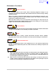
To remove KK type connectors:
❑ Free the locking mechanism on the connector by moving one side of the connector up, then
move the other side up (see the following diagram). The upward motion should only be as far
as needed to free the locking mechanism.
❑ DO NOT pull the cable to free the connector.
❑ Note that KK type connectors are designed to be removed in this manner to free the locking
mechanism. Do not use this procedure with non-KK type connectors as damage to the
connector may occur.
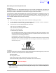
Top Cover
To remove the top cover, locate and unscrew the 18 countersunk screws securing the top cover to the
mainframe. Access can then be gained to the following modules:
❑ Processor module
❑ PSU Regulation module
❑ Power Supply (requires both top and bottom covers to be removed)
❑ Front Panel assembly (requires both top and bottom covers to be removed).
Dangerous voltages are present within the transceiver. Care must be taken by personnel to
avoid accidental contact with exposed circuitry when the top cover is removed and power is
applied to the radio.
Lift 2Lift 1
PCB
WARNING Dangerous Voltages