
User's Guide


Page 18
Back to Transceiver
Main Page
Fig 13
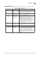
Fig 13 Example Phantom PTT Keying Diagram
Fig 14
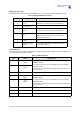
Fig 14 Example Phantom Squelch Indication Diagram
T6TR Transceiver
Audio lines with phantom PTT
signal superimposed
Solid state
relay
Reference can be configured as +14 V, 0 V
or -14 V from the Polarities screen.
With STD selected, PTT active when input
differs from reference by more than ±10 V.
PTT inactive when input differs from
reference by less than ±1 V.
With INV selected, PTT active when input
differs from reference by less than ±1 V. PTT
inactive when input differs from reference by
more than ±10 V.
For example, to use 0 volt as the keying
potential with STD polarity, set the reference
to +14 V or -14 V.
PTT
Maximum signal level ±60 V
with respect to transmitter
reference.
Internal Sensing Circuit
T6TR Transceiver
The pull-up voltage should be in the
range -60 to +60 V ac or dc.
R
Squelch Indicator
Audio lines with phantom
squelch signal superimposed
V
Solid state
relay
Relay = 100 mA maximum.
Can be configured as normally open, or
normally closed from the Polarities screen.