
User's Guide


Page 14
Back to Transceiver
Main Page
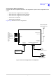
Connectors
Front and rear panel connector pin-outs are detailed in Table 4 to Table 11. The Reference connector is
described in text.
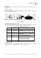
Front Panel Connectors
The front panel has two connectors; Headset/Microphone/Diagnostics connector and Reference
connector. These are illustrated in Fig 10.
Fig 10
Fig 10 Front Panel
Headset/Microphone/Diagnostics Connector
The Headset/Microphone/Diagnostic connector is shown in Table 4. This connector is a self-locking
7-way DIN socket used for connecting a microphone, microphone/headset or computer.
Reference Connector
The Reference connector is an SMB plug used to monitor the radio’s reference frequency. It monitors
the frequency at a level of 100 mV (±50 mV) with less than -10 dBc harmonics.
Table 4 Headset/Microphone/Diagnostics Connector
Pin Number Signal Characteristic
1 Microphone ground 0 V
2 Transmit data (output) RS232. 115200 baud, 8 data bits, 1 stop bit, no parity,
no handshaking.
3 Microphone PTT (input) 0 V to PTT.
4 Receive data (input) RS232. 115200 baud, 8 data bits, 1 stop bit, no parity,
no handshaking.
5 Sidetone/headset drive
(output)
The level is adjustable between 0 and 3 V
peak-to-peak by using the volume control.
6 Microphone input (input) To ensure correct VOGAD operation, the following
microphone input levels are required:
Passive setting: between 2 and 35 mV
Active setting: between 8 and 140 mV
7 Ground 0 V