
User's Guide


Page 5
Back to Transceiver
Main Page
Changing the Antenna Configuration (if required)
Dangerous voltages are present within the transceiver. Care must be taken by personnel to avoid
accidental contact with exposed circuitry when the bottom cover is removed and power is applied
to the radio
Proceed as follows:
(1) Remove the 15 captive screws securing the bottom cover to the mainframe.
(2) With the cover removed locate the PA Control/Rx RF module.
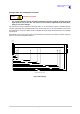
(3) Locate CN7 and CN12 on the PA Control/Rx RF module (see Fig 2).
(4) For single antenna configuration, connect the Rx antenna RF cable to CN12 (Park). Connect the
adjacent RF cable from the PA module to CN7.
(5) For dual antenna configuration, connect the Rx antenna RF cable to CN7. Connect the adjacent
RF cable from the PA module to CN12 (Park).
Fig 2 Antenna Configuration
Fig 2 Antenna Configuration
(6) When configured, replace the transceiver’s bottom cover using the 15 captive screws.
WARNING Dangerous Voltages
CN7
CN12
RX Antenna
PARK