
User's Guide


Page 25
Back to Transceiver
Main Page
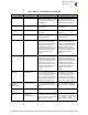
Table 8 AM-Voice and AM-MSK Polarity Settings
Signal Connector Polarity set to STD Polarity set to INV
Ready Out Facilities, pin 13 An open collector grounded
output when the radio is ready
to transmit and no BIT faults
are detected.
An open collector high
impedance output when the
radio is ready to transmit and
no BIT faults are detected.
E-BIT In Facilities, pin 2 TTL input. 0 V indicates an
external fault.
TTL input. 5 V indicates an
external fault.
Inhibit In Facilities, pin 10 TTL input. 0 V inhibits receiver
operation.
TTL input. 5 V inhibits receiver
operation.
BIT Start In Facilities, pin 11 TTL input. 0 V initiates an
interruptive BIT test.
TTL input. 5 V initiates an
interruptive BIT test.
PTT In MARC Audio, pin 8 Active when input differs from
reference by more than ±10 V.
Inactive when input differs from
reference by less than ±1 V.
Maximum input level ±60 V
with respect to reference. Input
will draw no more than 6 mA,
requires at least 1 mA to
operate.
Active when input differs from
reference by less than ±1 V.
Inactive when input differs from
reference by more than +10 V.
Maximum input level +60 V
with respect to reference. Input
will draw no more than 6 mA,
requires at least 1 mA to
operate.
Phantom PTT In MARC Audio, pin 4 Active when input differs from
reference by more than ±10 V.
Inactive when input differs from
reference by less than ±1 V.
Maximum input level ±60 V
with respect to reference. Input
will draw no more than 6 mA,
requires at least 1 mA to
operate.
Active when input differs from
reference by less than ±1 V.
Inactive when input differs from
reference by more than +10 V.
Maximum input level +60 V
with respect to reference. Input
will draw no more than 6 mA,
requires at least 1 mA to
operate.
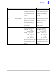
PTT Out Facilities, pin 3 Grounding solid state relay.
+60 to -60 V, ac or dc, 100 mA
max, n/o. Activated 20 ms
(±1 ms) before the start of the
power ramp up to allow for the
antenna relay to pull-in time.
Grounding solid state relay.
+60 to -60 V, ac or dc, 100 mA
max, n/c. Activated 20 ms
(±1 ms) before the start of the
power ramp up to allow for the
antenna relay to pull-in time.
Fast PTT Output
(antenna
changeover)
MARC Audio, pin 3 Open collector NPN transistor
grounding output, 200 mA max,
n/o.
Open collector NPN transistor
grounding output, 200 mA max,
n/c.
External VSWR
Input
Facilities, pin 4 TTL input. 0 V active. TTL input. 5 V active.
MARC squelch
out
MARC, pin 4
MARC audio, pin 6
Normally open relay contact
that closes to give a 0 V output
when the squelch circuits are
defeated (aircraft calling).
Normally closed (0 V output)
relay contact that opens when
the squelch circuits are
defeated (aircraft calling).