
User's Guide


Page 20
Back to Transceiver
Main Page
Removing and Refitting the Cooling Fan
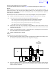
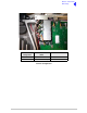
The cooling fan is at the rear of the PA module as shown in Fig 3. An assembly and removal diagram is
shown in Fig 10.
Removal
Before attempting to remove the fan, ensure that the transceiver is isolated from the ac and dc input
supplies. Then proceed as follows:
(1) Disconnect the two-pin connector.
(2) Remove fan's finger guard.
(3) Using an Allen key, inserted through the holes in the fan exposed with the finger guard removed,
remove the three M4 x 12 mm caphead Allen screws that secure the fan to the PA module
heatsink.
(4) Remove the fan from the PA module.
Refitting
To refit the cooling fan, proceed as follows:
(1) Locate the fan in position and using a suitable Allen key inserted through the holes for the fan's
finger guard, secure using the four M4 x 12 mm caphead Allen screws.
(2) Secure the finger guard to the fan.
(3) Connect the 2-pin fan connector to the fan. Ensure the + marked socket mates with the + marked
plug on the fan.
(4) Re-establish the ac and/or dc supplies.
(5) Switch power on at the radio using the rear mounted Power switch.
(6) Ensure the front panel Ready indicator is lit and the Alarm indicator is unlit.
(7) Carry out a BIT interruptive test as detailed in the procedure ‘To Initiate a BIT Test on page 7’.