
User's Guide


Back to Transmitter
Main Page
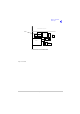
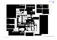
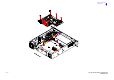
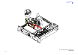
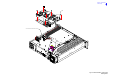
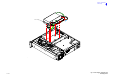
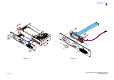
Fig 2 Wiring and Interconnection Diagram
CN2
Microphone/Diagnostics
Front P anel
CN3
CN1
Microphone /
Front Panel
Connections Name
Characteristic
CN2-1 1 Ground - Microphone 0 V
CN2-6
2 Transmit Data RS232
CN2-3 3
MIC PTT
CN2-4 4 Receive Data RS232
CN2-5 5 Sidetone (Headset Drive) 3 Vac pk-pk, 200R
CN2-2
6 Microphone I nput
CN2-7 7 Ground 0 V
CN4
CN5
Power Supply Regulation
CN2
1
2
2
3
1
CN3
1
3
2
CN1
4
dc I nput
Input-1 CN2-2
Fused 21.6 to 32 V
dc Input
In pu t-2 CN 2- 1 Ground S uppl y 0 V
Connections
DC Input Regulation
Name Characteristic
Input-3 n/c
Diagnostics
L
N
E
ac Input
CN1-3
CN1-2
CN1-1
Regulation
CN1-3
CN1-2
CN1-1
PSU
Connections
Ground Supply
Name Characteristic
CN1-4
0 V
CN3 CN4
CN7
Facilities
CN5
MARC
CN6
50
CN6
CN5
CN1
Processor
PA Control
Connections
CN2-1
Processor
n/c
Char acteri sticName
IF
Front Panel
Processor
Connections Name Characteristic
CN4-1
CN4-2
CN4-3
CN4-4
CN1-1
CN1-2
CN1-3
CN1-4
LED Alarm
LED Ready
LED Standby
LED Tx
LCD RS
Open collector (5mA)
CN4-5
CN4-6
CN4-7
CN4-8
CN4-9
CN4-10
CN4-11
CN4-12
CN4-13
CN4-14
CN4-16
CN4-17
CN4-18
CN1-20
CN1-19
CN4-15
CN1-25
CN4-24
CN4-23
CN1-22
CN1-21
CN1-5
CN1-24
CN1-23
CN1-16
CN4-19
CN4-22
CN4-21
CN4-20
CN1-18
CN1-17
CN1-6
CN1-7
CN4-25
LCD R/W
LCD Backlight
Transmit Data
+5 V Supply
-5 V Supply
Ground
+15 V Supply
Ground
Mic PTT
LED RX (not used)
5 V pull-up
TTL
TTL
TTL
TTL
0 V
-5 V
TTL
TTL
+1 5 V
LCD Enable
Data 3
Data 2
Data 7
Data 6
Data 5
Data 4
RS232
+5 V
0 V
34
CN3-14
CN3-13
CN3-12
CN3-11
CN3-10
CN4-14
CN4-13
CN4-12
CN4-11
CN4-10
n/c
Remote on/off
V Unreg
V Unreg
dc Detect
CN3-9
CN3-8
CN3-7
CN3-6
CN3-5
CN3-4
CN3-3
CN3-2
CN3-1
Connections
CN4-6
CN4-9
CN4-8
CN4-7
CN4-5
CN4-4
CN4-3
CN4-2
CN4-1
Regulation
ac Detect
-15 V Supply
Ground
+5 V Supply
+15 V Supply
Processor
Name Characteristic
+15 V Supply
-15 V Supply
+5 V Supply
Ground
-15 V
21.6 to 32 V
21.6 to 32 V
Open collector
15V on, 0V of f
+15 V
+5 V
+15 V
-15 V
+5 V
0V
0V
CN6-7
CN6-6
CN6-10
CN6-9
CN6-8
CN5-10
CN5-9
CN5-6
CN5-7
CN5-8
-15 V Supply
ac Detect
dc Detect
-15 V Supply
Ground
-15 V
-15 V
0V
Connections
CN6-5
CN6-4
CN6-3
CN6-2
CN6-1
CN5-2
CN5-4
CN5-3
CN5-5
Regulation
CN5-1
Name
+5 V Supply
+15 V Supply
+5 V Supply
+15 V Supply
Ground
PA Control
Characteristic
+15 V
+5 V
+5 V
0V
+15 V
*
*
CN6-7 7
CN6-8
CN6-9 9
8
Processor
CN6-1
CN6-2
CN6-3
CN6-5
CN6-6
CN6-4
**
4
6
5
3
1
2
MARC P ort
Connections
Data RX A - Data I n - RS422
RS422
RS422Data TX B - Data Out +
Data TX A - Data Out -
RS422
0 V or +10 V to +60 V or
Fused 500mA, 21.6 to 32 V
+20 dBm to -20 dBm 600R
Characteristic
PTT Input
Data RX B - Data In +
Unregulated Supply
Line In +
Ground
0 V
Name
+20 dBm to -20 dBm 600R
**
CN5-4
CN5-6
CN5-7
CN5-5
7
5
6
4
Grounding output +/- 60V,
100mA max.
TT L pu ll -up active low
Grounding output +/- 60V,
100mA max.
S quelch Defea t (not used)
Antenna Change Over
External VSWR
CN5-3
CN5-2
CN5-1
Processor
Connections
Facilities
2
3
1
TT L pu ll -up active low
CharacteristicName
E Bit
PTT
Ground 0 V
Ground
Unregulated Supply
CN5-8
CN5-9
9
80 V
Fused 300mA 21.6 to 32 V
Grounding output +/- 60V,
100mA max.
Name
Reserved
Tape Output
CN5-14
CN5-15
CN5-13
CN5-12
CN5-11
14
15
13
12
11 BIT Interruptive Test
RSSI (not used)
Ready Output
Facilities
Connections
CN5-10
Processor
10 Inhibit
Open collector, 0 V = Ready
-10 dBm. 100R
TT L pull-up active low
Characteristic
***
V Unreg
Receive Data
0 V=PTT,5 V pull-up=PTT
Turn +
TTL
TTL
TTL
RS232
Turn -
Sidetone (Headset Drive) 3 Vac pk-pk
Loudspeaker Amp Drive
Ground
Mic Input
Ground 0V
1.6V p-p maximum
0V
2V p- p ma x imum
Push
Ground 0 V
CN1-26CN4-26
CN1-27CN4-27
CN1-31
CN1-29
CN4-28
CN1-30
CN4-31
CN4-29
CN1-28
CN4-30
CN4-33
CN1-34
CN1-33
CN4-34
CN1-32CN4-32
Open collector (200mA)
0V = off, open collector = on
n/c
n/c
n/c
n/c
n/c
CN2
CN1
CN3
CN4
CN2
CN3-1
CN3-2
Front Panel
Characteristic
Ground
Connections
Loudspeaker Output
Name
0 V = PT T, 5 V pull -up = not PTT
6k8 input impedance, 5mV sensitivity
CN10
CN1
6
Fan
2
PA
Reference Frequency
Connections
Front P anel
-20 dBm to 0 dBm
CharacteristicName
CN5-1
Forward Power Sense CN8
Connections
17 dBm ± 1 dB
Name Characteristic
RF Output
Connections
PA
CN1-1
Name Characteristic
5 to 50 W
CN4-1
Antenna Port
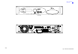
(Rear Panel)
CN8
Open collector (5mA)
Open collector (5mA)
Open collector (5mA)
Data 1
Data 0
TTL
TTL
CN1-12
CN1-13
CN1-14
CN1-15
CN1-8
CN1-9
CN1-10
CN1-11
5 V pull-up
5 V pull-up
RF PA
1 dBm carr ierRF DriveCN10CN3-1
Connections Name Characteristic
RF PA
PA Heatsink
CN6
Fan Control
Ground 0V
10V approx. or 26.5V
CharacteristicConnections Name
Fan
Fan
-10 V to -60 V at 6mA
TT L pull-up active low
Regulator
Connections
RF PA
Name
Characteristic
CN3-1
CN3-2
CN3-3
Heatsink
CN3 V Unreg
-33 V
Ground Supply
21.6 to 32 V
0 V
n/c
10
14
3
CN3-3
n/c n/c
CN5
CN4
Reference Frequency
(Front Panel)
CN4-1
CN3
CN2
CN4
CN5
CN7
CN9
CN6
(-30.5 dBc ± 0.9 dB)
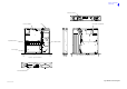
Mains IEC
Connector
Filtered/
Fused
0 to 4 V / 0 to 6VFrequency TrimCN1-14 CN1-14
CN1-50
CN1-48
CN1-49
CN1-47
CN1-45
CN1-46
CN1-44
CN1-43
CN1-42
CN1-41
CN1-15
CN1-16
CN1-21
CN1-22
CN1-23
CN1-17
CN1-19
CN1-18
CN1-20
CN1-24
CN1-25
CN1-30
CN1-26
CN1-29
CN1-28
CN1-27
CN1-31
CN1-32
CN1-33
CN1-34
CN1-36
CN1-35
CN1-37
CN1-40
CN1-39
CN1-38
CN1-50
CN1-45
CN1-43
CN1-44
CN1-47
CN1-46
CN1-49
CN1-48
CN1-28
CN1-42
CN1-41
CN1-38
CN1-39
CN1-36
CN1-37
CN1-40
CN1-32
CN1-31
CN1-29
CN1-30
CN1-34
CN1-33
CN1-35
CN1-21
CN1-24
CN1-23
CN1-22
CN1-26
CN1-27
CN1-25
CN1-17
CN1-16
CN1-15
CN1-20
CN1-19
CN1-18
TTL
TTL
TTL
TTL
TT L - Low OCXO fitted
TTL - High fan on
TTL
BIT Control 3 (Not used)
BIT Control 2 (Not used)
Step Size (Not used)
V/U Detect
TR Detect
Reserved
OCXO Fitted
Fan Enable
TTL
TTL
TTL
TTL
TTL
TTL
0 to 2.5 V
10 mV / °C
10 mV / °C
0 to 5 V (5 V 3dB back off)
TTL
TTL
TTL
TTL
TTL
BIT Loop Correct
BIT Synth Lock
BIT Open Loop
BIT V SW R OK
BIT Control 1
BIT Control 0
Reflected Power
PA Temperature
Auto Level Control
External V SWR
PAC Temperature
Narrow/Wide (Not used)
Tx Key
TTL
TTL
TTL
TTL
0 V
TTL
0 V
TT L pull up active low
TTL
TTL
TTL
TTL
Filter 3
Data
Phase Load
Clock
Synth Load
Ground
Filter 4
Filter 0
Filter 2
Filter 1
Ground
Power Down
Tx/Rx Detect
CN1-10
CN1-13
CN1-12
CN1-11
PA ControlProcessor
CN1-7CN1-7
CN1-9
CN1-10
CN1-8
CN1-12
CN1-13
CN1-11
CN1-9
CN1-8
CN1-2
CN1-3
CN1-1
CN1-5
CN1-6
CN1-4
CN1-6
CN1-5
CN1-4
CN1-2
CN1-3
CN1-1
Connections
0 to 2.5 V
0 V
±2.5 V
±2.5 V
0 to 2.5 V
0 to 2.5 V
0 to 2.5 V
0 V
0 V
0 V
0 V
0 V
0 V
Ground
Ground
Q
Ground
Ground
BIT Q Monitor
BIT I Monitor
RF AGC (Not used)
I
Ground
IF AGC (Not used)
Ground
Ground
Name Characteristic
***
A B C D
CN8
Processor
CN8 Ring
CN8 Tip
External Speaker Drive
External Speaker Drive 3 Vac pk-pk max
Characteristic
Connections Name
External Speaker
1
2
CN8 Sleeve Ground 0 V
3
3 Vac pk-pk max
Antenna Change Over
TTL pull-up active low
Potential range 0 V to 10 V
6
7
8
2
4
3
5
Pin Number
1
Name
CN7A
CN7ACN7A
CN7A
n/c
n/c
n/c
RTIP
TRING
n/c
TTIP
RRING
*
6
7
8
2
4
3
5
Pin Number
1
Name
CN7B
CN7BCN7B
CN7B
HDLC CL B
HDLC CL A
Unregulated Supply
HDLC R x B
HDLC Tx B
HDLC Rx A
HDLC Tx A
Ground
6
7
8
2
4
3
5
Pin Number
1
Name
CN7C
CN7CCN7C
CN7C
n/c
Unregulated Supply
Data Rx B (Data In +)
Data T x B (Dat a Out +)
Data Rx A (Data In -)
Data T x A (Data Out -)
Ground
*
6
7
8
2
4
3
5
Pin Number
1
Name
CN7D
CN7DCN7D
CN7D
Not used
Fast Antenna Change Over /
PTT
Not used
Line In +
PTT Input
Line In -
Not used
Ground
*
Characteristic
Char acteri stic
Char acteri stic
Characteristic
+20 dBm to -20 dBm 600R
+20 dBm to -20 dBm 600R
0 V
0 V or +10 V to +60 V or
-10 V to -60 V at 6mA
+20 dBm to -20 dBm 600R
+20 dBm to -20 dBm 600R
ANSI T1.403-1995 (T1),
ITU-T: G.703 (E1)
ANSI T1.403-1995 (T1),
ITU-T: G.703 (E1)
NPN open collector
grounding transistor
0 V or +10 V to +60 V or
-10 V to -60 V at 6mA
0V
RS 422
RS 422
RS 422
RS 422
RS 422
RS 422
21.6V to 32V
Reserved
RF PA Bias Disable
TTL
0 V
7.5V pk-pk Max
Open collector (5mA)
EXT
SPKR
T1/E1
MARC AUDIO
MARC DAT A
HDLC
TTL
RF PA
PA Control
PA Control
PA Control
0V
21.6V to 32V
RS 422
RS 422
RS 422
RS 422
13
(Rear Panel)
CN7
2
Supply
(shown in
off position)
CN8
1 L
2 N
3
E
Power Supply
1
CN1
4
3
2
L
N
E
CN6
CN1-4
CN4
CN9
L
N
0 V
Characteristic
0 V = on
o/c OK
PSU OKCN6-3
CN6-5
CN6-4
0 V
PSU off
PSURegulation
Connections Name
CN6-6
CN6-2
CN6-1
0 V
PSU OK
0 V
0 V OK
CN4-3
CN4-1
PSU off PSU off 0V = 0ff
2
2
(Rear Panel)
Ground Supply 0 V
29 V
V Unreg
29 V
R emote Supply On/Off
Line In -
50 W = 670 mV
Characteristic
TT L - High for fan on
TTL - High for bias on
PA Bias EnableCN2-3
CN2-5
CN2-4
Reflected Power
Fan Enable
RF PA
Connections Name
CN2-6
CN2-2
CN2-1
PA Temperature
Drive Detect
10 mV/°C + 0.5V
0.5 V for +10 dBm
CN4
CN9
CN5
CN7
CN2
CN12 PA Current Detect (not used) 0.1V per Amp
PA Control
CN12
T6S2VHF Tx Interconnection and Wiring