
User's Guide


T6T 50 W VHF Transmitter Page 16 Maintenance
Back to Transmitter
Main Page
(7) Remove the Front Panel PCB from the Front Panel assembly by removing the six M3 x 6 mm
panhead screws and wavy washers (see Fig 9 Diagram B).
Refitting
To refit the Front Panel assembly PCB, proceed as follows:
(1) Place the PCB in position at the Front Panel assembly. Ensure the spindle of the control knob
and microphone/diagnostics connector are correctly located. Secure the PCB to the Front Panel
assembly using the six M3 x 6 mm panhead screws and wavy washers (see Fig 9, Diagram B).
(2) At the front panel, place the control knob onto the spindle and using a 1.5 mm Allen key, secure
the Allen head grub screw.
(3) Secure the Front Panel assembly to the top and bottom of the mainframe box section using the
four M3 x 8 mm countersunk screws. Fit the two black equipment handles using the four
M5 x 16 mm panhead screws (see Fig 9, Diagram A).
(4) Route the ribbon cable to the Processor module connector CN4 and connect it.
(5) Route the SMB connector to CN5 on the PA Control module and connect it.
(6) Re-establish the ac and/or dc supplies.
(7) Switch power on at the radio using the rear mounted Power switch.
(8) Ensure the front panel Ready indicator is lit and the Alarm indicator is unlit.
(9) Carry out a BIT interruptive test as detailed in the procedure To Initiate a BIT Test on page 5.
(10) Switch power off at the transmitter using the rear mounted Power switch. Isolate the transmitter
from the ac and/or dc supplies.
(11) Refit the transmitter’s top and bottom covers. The transmitter can now be returned to service.
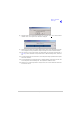
Removing and Refitting the Cooling Fan
The cooling fan is at the rear of the PA module as shown in Fig 3. An assembly and removal diagram is
shown in Fig 10.
Removal
Before attempting to remove the fan, ensure that the transmitter is isolated from the ac and dc input
supplies. Then proceed as follows:
(1) Disconnect the two-pin connector.
(2) Remove fan's finger guard.
(3) Using an Allen key, inserted through the holes in the fan exposed with the finger guard removed,
remove the three M4 x 12 mm caphead Allen screws that secure the fan to the PA module
heatsink.
(4) Remove the fan from the PA module.
Refitting
To refit the cooling fan, proceed as follows:
(1) Locate the fan in position and using a suitable Allen key inserted through the holes for the fan's
finger guard, secure using the three M4 x 12 mm caphead Allen screws.
(2) Secure the finger guard to the fan.