
User's Guide

T6T 50 W VHF Transmitter Page 11 Maintenance
Back to Transmitter
Main Page
(13) Remove the VFP connector and switch power off at the transmitter using the rear mounted
Power switch. Isolate the transmitter from the ac and/or dc supplies.
(14) Refit the transmitter’s top cover (take note of repairs caution (1) on page 7 before carrying out
this task). The transmitter can now be returned to service.
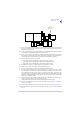
Removing and Refitting the PSU Regulator Module
The PSU Regulator module is located as shown in Fig 3. A module removal diagram is shown in Fig 5.
Removal
Before attempting to remove the PSU Regulator module, ensure that the transmitter is isolated from the
ac and dc input supplies. Then proceed as follows:
(1) Remove the transmitter’s top cover as described on page 9 (take heed of the warning).
(2) Locate the PSU Regulator module and remove the three M3 x 8 mm captive washer screws that
secure the module to the transmitter’s mainframe.
(3) Carefully raise the module to gain access to the module connectors.
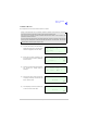
(4) Disconnect the following connectors:
❑ CN5 10-way connector (10-way ribbon cable to PA Control module)
❑ CN6 6-way connector (2-way loom to power supply). Note caution (3) on page 8
❑ CN4 14-way connector (14-way ribbon cable to Processor module)
❑ CN3 3-way connector (3-wire loom to PA module)
❑ CN7 3-way connector (3-wire loom to rear panel On/Off switch). Note caution (3) on page 8
❑ CN2 2-way connector (2-wire loom from dc input connector on rear panel)
❑ CN1 4-way connector (4-wire cable from power supply)
❑ CN9 2-way connector (2-wire cable ac input to power supply)
❑ CN8 3-way connector (2-wire loom to rear panel ac input connector plus chassis connection).
(5) Remove the module from the chassis.
Refitting
To refit the PSU Regulator module, proceed as follows:
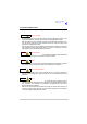
(1) While holding the module in position, connect the following connectors:
❑ CN8 3-way connector (2-wire loom to rear panel ac input connector plus chassis connection)
❑ CN9 2-way connector (2-wire cable ac input to power supply)
❑ CN1 4-way connector (4-wire cable from power supply)
❑ CN2 2-way connector (2-wire loom from dc input connector on rear panel)
❑ CN7 3-way connector (3-wire loom to rear panel On/Off switch)
❑ CN3 3-way connector (3-wire loom to PA module)
❑ CN4 14-way connector (14-way ribbon cable to Processor module)
❑ CN6 6-way connector (2-way loom to power supply)
❑ CN5 10-way connector (10-way ribbon cable to PA Control module).
(2) Locate the module in position. Ensure no wires are trapped by the module.