
User's Guide

T6T 50 W VHF Transmitter Page 10 Maintenance
Back to Transmitter
Main Page
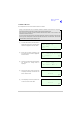
(1) Ensure the module’s interface connectors CN5 and CN6 are located correctly and are aligned
with the screw holes in the rear panel. Fit the four screwloc 8 mm-4-40 UNC screws and wavy
washers but leave them loose.
(2) Fit the 11 (Mod Strike 5 modules), 7 (Mod Strike 6 and 7 modules) M3 x 8 mm screws that secure
the module to the transmitter’s mainframe, but leave them loose.
(3) Using a 5 mm nut spinner, tighten the four screwloc 8 mm-4-40 UNC screws and wavy washers
that secure the connectors; then tighten the 11 (Mod Strike 5 modules), 7 (Mod Strike 6 and 7
modules) M3 x 8 mm screws that secure the module to the transmitter’s mainframe.
(4) Refit the following connectors to the module:
❑ CN1 50-way connector (50-way ribbon cable from PA Control module).
❑ CN3 14-way connector (14-way ribbon cable from PSU Regulator module).
❑ CN4 34-way connector (34-way ribbon cable from Front Panel module).
(5) Re-establish the ac and/or dc supplies (take heed of the warning on page 9).
(6) Switch power on at the radio using the rear mounted Power switch.
(7) Ensure the front panel Ready indicator is lit and the Alarm indicator is unlit.
(8) If a new module has been fitted, connect the VFP PC to the radio using the PC to Radio
Interconnection Lead, Park Air part number 17E12600001 (if not already connected). Note that
any module sent from Park Air as a spare for a particular radio will be programmed with
compatible operating and Fill software. Park Air keeps records of module software in all radios
supplied. Care must be taken when using a module removed from another radio as this module
may not have compatible software.
(9) Download the saved radio settings from file using the VFP. Alternatively, the settings can be
edited by hand as described in the Operation section of this
document Once entered, ensure the required settings appear in the VFP screen.
(10) Carry out the Calibrate routine using the VFP, as detailed in the procedure To Calibrate the
Transmitter on page 22.
(11) Carry out a BIT interruptive test as detailed in the procedure To Initiate a BIT Test on page 5.
(12) Set the transmitter’s internal reference frequency by carrying out the procedure detailed on
page 3.
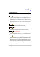
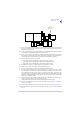
IC25
T2
C84
TS7
T3
IC27
JP2
Shown set for
transmitter
T
T
R/TR
R/TR
IC21
IC20IC19
IC38