
User's Guide

T6T 50 W VHF Transmitter Page 9 Maintenance
Back to Transmitter
Main Page
Top Cover
To remove the top cover, locate and unscrew the 18 countersunk screws securing the top cover to the
mainframe. Access can then be gained to the following modules:
❑ Processor module
❑ PSU Regulation module
❑ Power Supply (requires top cover and bottom cover to be removed)
❑ RF PA module (requires top cover and bottom cover to be removed)
❑ Front Panel assembly PCB (requires top cover and bottom cover to be removed)
Removing and Refitting the Processor Module
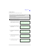
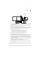
The Processor module is located as shown in Fig 3. A module removal diagram is shown in Fig 4.
Dangerous voltages are present within the transmitter. Care must be taken by personnel to
avoid accidental contact with exposed circuitry when the top cover is removed and power is
applied to the radio.
Removal
Before attempting to remove the Processor module, and if possible, save the radio’s settings. To achieve
this connect a PC with the VFP software loaded to the radio using the PC to Radio Interconnection Lead
(Park Air part number 17E12600001). With the VFP software active, upload the radio settings to a
specified file.
Ensure that the transmitter is isolated from the ac and dc input supplies. Then proceed as follows:
(1) Unscrew the 18 countersunk screws and remove the transmitter’s top cover.
(2) Locate the Processor module (Fig 3) and disconnect the following connectors (Fig 4):
❑ CN1 50-way connector (50-way ribbon cable from PA Control module)
❑ CN3 14-way connector (14-way ribbon cable from PSU Regulator module)
❑ CN4 34-way connector (34-way ribbon cable from Front Panel module).
(3) Gain access to the rear of the transmitter. Using a 5 mm nut spinner tool, remove the four
screwloc 8 mm-4-40 UNC screws that secure the Processor module interface connectors CN5
and CN6 to the rear panel.
(4) Remove the seven M3 x 8 mm screws that secure the module to the transmitter’s mainframe.
(5) Remove the module from the chassis.
Refitting
To refit the Processor module, proceed as follows:
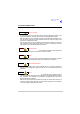
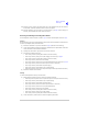
(1) Place the module in position. Ensure no wires are trapped by the module. Ensure jumper J2 on
the module is set to ‘T’ for transmitter (see the following diagram).
WARNING Dangerous Voltages