
User's Guide

T6T 50 W VHF Transmitter Page 8 Maintenance
Back to Transmitter
Main Page
Introduction
This document provides the user with detailed instructions on the removal and replacement of modules
and assemblies.
(1) When removing or refitting modules, observe antistatic handling precautions.
(2) Do not change any potentiometer (or link) settings unless detailed in these instructions.
Potentiometers have been set using specialist equipment.
(3) The transmitter uses the following Molex KK connectors:
CN2 on the PA Control module
CN7 and CN6 on the PSU Regulator module.
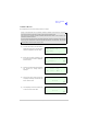
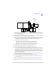
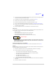
To remove KK type connectors:
❑ Free the locking mechanism on the connector by moving one side of the connector up, then
move the other side up (see the following diagram). The upward motion should only be as far
as needed to free the locking mechanism
❑ DO NOT pull the cable to free the connector
❑ Note that KK type connectors are designed to be removed in this manner to free the locking
mechanism. Do not use this procedure with non-KK type connectors as damage to the
connector may occur.
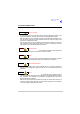
Tools, Materials and Test Equipment Required
The following tools, materials and test equipment should be made available to complete the
maintenance tasks described in this section:
❑ Personal Computer (PC)
❑ General Purpose Tool kit (including a
1.5 mm Allen key)
❑ 5 mm Nut Spinner
❑ Camel Hair Brush
❑ Clean Lint-free Cloths
❑ Frequency Counter
❑ Power Meter
❑ Dummy Load
❑ PC to Radio Interconnection Lead
(Park Air part number 17E12600001)
❑ SMB to BNC Lead for reference frequency
(Park Air part number 17K11000004)
Lift 2Lift 1
PCB