
User's Guide


T6T VHF 50 W Transmitter Page 22 Installation
Back to Transmitter
Main Page
Chassis Stud Connection
A chassis stud is fitted to the transmitter's rear panel. This stud is used to connect the
equipment to the equipment cabinet, or to the user's system earth point. The stud must not
be used as the safety earth.
In order not to compromise the transmitter’s Electromagnetic Compatibility (EMC) the chassis stud,
marked and fitted to the rear panel (see Fig 8) must be connected to the equipment cabinet (if a
cabinet is being used) or to the user's system earth point. The connection should be made using a single
tri-rated, green-and-yellow cable having a cross-sectional area of 2.5 mm
2
. The cable should have CSA
and UL1015 approval, and be connected to the chassis stud through an M6 eyelet (for example, Park Air
part number 20-08010103).
Failure to comply with this instruction could result in non-compliance with the European
Commission EMC Directive 89/336/EEC.
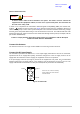
Connect the Antenna
The antenna connector is an N-type socket suitable for connecting a 50 ohm antenna.
Connect the DC Input Supply
The transmitter operates from either an ac, or a dc input supply. When both ac and dc are connected,
operation from the ac supply takes priority; automatic change-over to the dc supply occurs if the ac
supply fails. On restoration of the ac supply, the equipment reverts to ac operation.
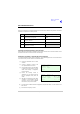
A dc input supply connector (see Fig 12) is fitted to the equipment's rear panel. The recommended
minimum rating of the dc supply cable is: 2-core having a cross-sectional area of 1.5 mm
2
per core. The
supply cable should be fitted with an XLR 3-pin socket (Park Air part number 20-01030106).
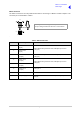
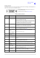
Fig 12 DC Connector
WARNING Chassis Earth
Positive Negative
Not used
Pin-out of DC connector looking
into the mating face of the chassis
mounted socket.