
User's Guide

T6T VHF 50 W Transmitter Page 10 Installation
Back to Transmitter
Main Page
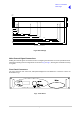
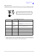
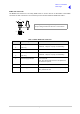
Fig 6 Slide Fittings
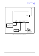
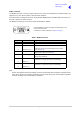
Make External Signal Connections
Making the external signal connections involves configuring the transmitter to suit its operational mode.
Illustrations showing various configurations are shown in Fig 1 to Fig 5; these figures should be used only
as a guide.
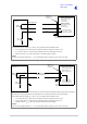
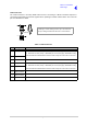
Front Panel Connectors
The front panel has two connectors; Microphone/Diagnostics and Reference connectors. These are
illustrated in Fig 7.
Fig 7 Front Panel
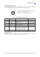
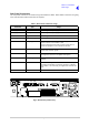
Front
Panel
399
390.9
378.2
232.2
207.5
152.8
47.0
29.0
41.7
430
88.9
450
All measurements in mm