
User's Guide

T6T VHF 50 W Transmitter Page 9 Installation
Back to Transmitter
Main Page
Installation Procedures
Initial Inspection of the Transmitter
On receipt of the transmitter, remove all transit packaging and check that there is no damage. If damage
is evident, contact Park Air immediately and retain the original transit packaging. One copy of the T6 User
Guide CD (part number 31-36T62VCD) is normally supplied with the transmitter. This CD includes the
VFP software.
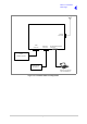
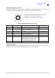
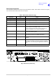
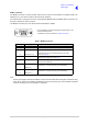
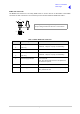
Fitting the Correct AC Input Fuse
The mains input fuse F2 is an integral part of the rear panel ac connector. The fuse type must be correct
for the local mains supply as detailed below.
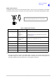
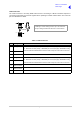
Fitting a Radio into an Equipment Cabinet
It is essential that the chosen mechanical installation provides adequate support along the
depth (front to rear) of the unit. The transmitter must not be supported by the front panel;
doing so can cause damage.
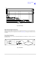
The transmitter can be installed on telescopic slides, or on fixed runners, within a standard 483 mm
(19 inch) equipment cabinet. M4 tapped holes, each 10 mm deep (see Fig 6) are provided on each side
of the equipment to accept the slides. Details of suitable telescopic slides and fixed runners are available
from Park Air.
When fitted in the cabinet, the transmitter's front panel must be secured to the cabinet’s chassis using
four M6 x 16 mm screws and plastic washers.
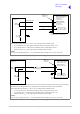
FS2
Spare Fuse
Line
Neutral
Earth
For a mains input in the range 110 to 120 Vac, fuse
F2 should be rated T4A, 125V, UL.
For a mains input in the range 110 to 240 Vac, fuse
F2 should be rated T4A, 250V, IEC.
Holder for spare
fuse (not supplied)
Caution Mechanical Support