
User's Guide


T6T VHF 50 W Transmitter Page 26 Operation
Back to Transmitter
Main Page
Mode 2 and Mode 3 BIT Screen
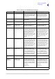
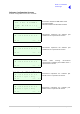
The Mode 2 and Mode 3 BIT screen is accessed from the Control screen.
E T I 0 0 0 0 0 : 0 0 h r s
A C S u p p l y O N
D C S u p p l y O N
E x i t > >
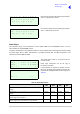
S u p p l y 2 8 V
S y n t h L o c k P A S S
P A T e m p 5 0 d e g C
E x i t < < > >
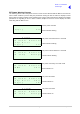
P A C o o l i n g P A S S
V S W R P A S S
L o o p E r r o r P A S S
E x i t < < > >
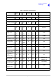
D S P 1 P A S S
D S P 2 P A S S
X i l i n x 1 P A S S
E x i t < < > >
X i l i n x 2 P A S S
E E P R O M P A S S
S t a r t U p P A S S
E x i t < < > >
C a l i b r a t i o n P A S S
E - B I T P A S S
M A R C A C T I V E
E x i t < < > >
Shows elapsed time 0:00 to 99999:59 (Hrs:Min).
Shows state of ac supply (On or Off).
Shows state of dc supply (On or Off).
Shows value of dc supply.
Synth lock (Pass or Fail).
Indicates the PA temperature.
Pass or Fail.
Pass or Fail.
Pass or Fail.
Pass or Fail.
Pass or Fail.
Pass or Fail.
Pass or Fail.
Pass, Fail or Not Tested.
Pass or Fail.
Pass or Fail.
Pass or Fail.
Active or Inactive.
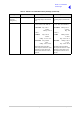
H D L C I N A C T I V E
T 1 / E 1 I N A C T I V E
B a c k
E x i t < <
Active or Inactive.
Active or Inactive.