
User's Manual Part 2
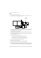
Table Of Contents
- Maintenance
- Introduction
- Scheduled Maintenance
- Unscheduled Maintenance
- Introduction
- Tools, Materials and Test Equipment Required
- T6T VHF Amplifier Procedures
- Top and Bottom Covers
- Removing and Refitting the Interface Module
- Removing and Refitting the PSU Regulation Module
- Removing and Refitting the Power Supply Modules
- Removing and Refitting the Combiner BIT Module
- Removing and Refitting the PA Modules
- Removing and Refitting the Front Panel PCB
- Removing and Refitting the Cooling Fans
- T6T VHF Drive Assembly Procedures
- Removing the Top Cover
- Removing and Refitting the Processor Module
- Removing and Refitting the PSU Regulation Module
- Removing and Refitting the Drive Module
- Removing the Bottom Cover
- Removing and Refitting the PA Control Module
- Removing and Refitting the Power Supply
- Removing and Refitting the Front Panel PCB
- Virtual Front Panel (VFP)

T6T 300 Watt VHF Transmitter Page 116 Maintenance
T6T VHF Drive Assembly Procedures
Removing the Top Cover
Dangerous voltage is present within the T6T VHF drive assembly. Care must be taken by
personnel to avoid accidental contact with exposed circuitry when the covers are removed
and power is applied to the radio.
To remove the top cover, ensure that the drive assembly is isolated from the ac and dc input supplies.
Then locate and unscrew the 13 screws securing the top cover to the mainframe. Access can then be
gained to the following modules:
❑ Processor module
❑ PSU Regulation module
❑ Drive module
❑ Power Supply (requires top and bottom covers to be removed)
❑ Front Panel assembly PCB (requires top and bottom covers to be removed).
Removing and Refitting the Processor Module
The Processor module is located as shown in Fig 44. A module removal diagram is shown in Fig 46.
Dangerous voltage is present within the T6T VHF drive assembly. Care must be taken by
personnel to avoid accidental contact with exposed circuitry when the covers are removed
and power is applied to the radio.
Removal
Before attempting to remove the Processor module, and if possible, save the drive assembly settings.
To achieve this connect a PC with the VFP software loaded to the radio using the PC to Radio
Interconnection Lead (Park Air part number 17E12600001). With the VFP software active, upload the
radio settings to a specified file.
Ensure that the drive assembly is isolated from the ac and dc input supplies. Disconnect the six Amplifier
Out connectors, CN1 to CN6. Then proceed as follows:
(1) Unscrew the 13 countersunk screws and remove the drive assembly top cover.
(2) Locate the Processor module (Fig 44) and disconnect the following connectors:
❑ CN1 50-way connector (50-way ribbon cable from PA Control module)
❑ CN12 2-way connector (2 wire loom from Drive module CN11)
❑ CN3 14-way connector (14-way ribbon cable from PSU Regulation module)
❑ CN4 34-way connector (34-way ribbon cable from Front Panel module).
(3) Gain access to the rear of the drive assembly. Using a 5 mm nut spinner tool, remove the four
screwloc 8 mm-4-40 UNC screws that secure the Processor module interface connectors CN5
and CN6 to the rear panel.
(4) Remove the seven M3 x 8 mm screws that secure the module to the drive assembly mainframe.
WARNING Dangerous Voltage
WARNING Dangerous Voltage