
User's Manual Part 1
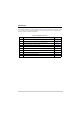
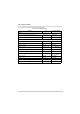
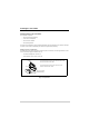
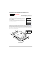
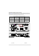
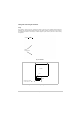
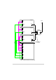
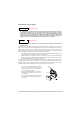
Table Of Contents
- Health and Safety
- Customer Support
- Abbreviations
- Overview
- Specification
- Operation
- Overview
- T6T VHF Amplifier
- Drive Assembly
- Setting Up and Operation
- Normal Operation
- Using the Scroll/Select Switch
- Screen Protocol
- Menu System
- Menu Lock Screen
- Control Screen
- Notes for Setting Up the Transmitter
- Changing the Transmitter’s Operating Frequency
- To Store and Recall Frequency Channels
- To Initiate a BIT Test
- Standby Mode
- Settings
- AM-Voice Settings Procedure
- AM-MSK Mode Settings Procedure
- Mode 2 Settings Screen
- Mode 3 Settings Screen
- Polarities Screen AM-Voice and AM-MSK
- Mode 2 and Mode 3 Polarity Settings
- AM-Voice and AM-MSK BIT Screen
- Mode 2 and Mode 3 BIT Screen
- Software Configuration Screens
- Band Edges
- BIT Status Warning Screens
- Installation
- Warnings and Cautions
- Introduction
- Installing the Transmitter

T6T 300 Watt VHF Transmitter Page 78 Installation
Connecting the AC Input Supply
The equipment is permanently connected to the mains supply when the mains connectors
are attached. Switching the rear panel Supply switch to off does not isolate all internal
circuits from the mains supply. For this reason, a mains isolating switch should be fitted
close to, and easily accessible from, the transmitter's position. The isolation switch should
isolate both live and neutral supplies to the IEC connectors fitted to the drive assembly and
amplifiers, be clearly labelled, and adequately rated to protect the equipment.
This equipment must be earthed. The earth terminal of the ac connector should be used as
the safety earth.
Two ac input connectors are fitted to each amplifier rear panel, and one to the drive unit rear panel. The
cables used to connect between the equipment and the ac power source should be 3-core (to IEC 227)
rated 250 Vac at 8 amps, and have a minimum cross-sectional area of 1.0 mm
2
per core. Park Air
recommends the use of polyvinyl chloride (PVC) insulated cable. The cable must be fitted with the IEC
approved equipment connector and conform to the following specification:
❑ If PVC insulated, be not lighter than ordinary polyvinyl chloride sheathed flexible cord according
to IEC publication 227 (designation H05 VV-F, or H05 VVH2-F)
❑ If rubber insulated, be of synthetic rubber and not lighter than ordinary tough rubber-sheathed
flexible cord according to IEC publication 245 titled ‘Rubber Insulated Cables of Rated Voltages
up to and Including 450/750 V (designation H05 RR-F)’.
The T6T 300 W transmitter is a Class 1 equipment. The ac supply cables should have a green-and-
yellow protective earthing conductor electrically connected to the protective earthing terminal of the
equipment connector and the mains plug. Park Air recommends the ac supply cable is colour coded in
accordance with the electrical appliance (colour code) regulations for the UK. That is:
WARNING Dangerous Voltage
WARNING Earth Connection
FS2
Spare
Line
Neutral
Earth
❑ The core coloured green-and-yellow must be
connected to the terminal in the plug that is
marked with the letter E or by the earth symbol
or coloured green-and-yellow
❑ The core coloured blue must be connected to
the terminal that is marked with the letter N or
coloured black
❑ The core coloured brown must be connected to
the terminal that is marked with the letter L or
coloured red.
Fuse