
User's Manual Part 1
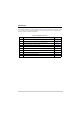
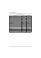
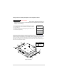
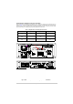
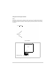
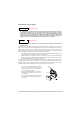
Table Of Contents
- Health and Safety
- Customer Support
- Abbreviations
- Overview
- Specification
- Operation
- Overview
- T6T VHF Amplifier
- Drive Assembly
- Setting Up and Operation
- Normal Operation
- Using the Scroll/Select Switch
- Screen Protocol
- Menu System
- Menu Lock Screen
- Control Screen
- Notes for Setting Up the Transmitter
- Changing the Transmitter’s Operating Frequency
- To Store and Recall Frequency Channels
- To Initiate a BIT Test
- Standby Mode
- Settings
- AM-Voice Settings Procedure
- AM-MSK Mode Settings Procedure
- Mode 2 Settings Screen
- Mode 3 Settings Screen
- Polarities Screen AM-Voice and AM-MSK
- Mode 2 and Mode 3 Polarity Settings
- AM-Voice and AM-MSK BIT Screen
- Mode 2 and Mode 3 BIT Screen
- Software Configuration Screens
- Band Edges
- BIT Status Warning Screens
- Installation
- Warnings and Cautions
- Introduction
- Installing the Transmitter

T6T 300 Watt VHF Transmitter Page 77 Installation
Connecting the Chassis Stud
A chassis stud is fitted to each amplifier’s rear panel and to the drive assembly. This stud is
used to connect the equipment to the equipment cabinet, or to the user's system earth point.
The stud must not be used as the safety earth.
In order not to compromise the transmitter’s Electromagnetic Compatibility (EMC) the chassis stud,
marked and fitted to the rear panel must be connected to the equipment cabinet (if a cabinet is being
used) or to the user's system earth point. The connection should be made using a single tri-rated, green-
and-yellow cable having a cross-sectional area of 2.5 mm
2
. The cable should have CSA and UL1015
approval, and be connected to the chassis stud through an M6 eyelet (for example, Park Air part number
20-08010103).
Failure to comply with this instruction could result in non-compliance with the European
Commission EMC Directive 89/336/EEC.
Connecting the DC Input Supply
The transmitter operates from either an ac, or a dc input supply. When both ac and dc are connected,
operation from the ac supply takes priority; automatic change-over to the dc supply occurs if the ac
supply fails. On restoration of the ac supply, the equipment reverts to ac operation.
Two dc input supply connectors (see Fig 18) are used on each amplifier and one on the drive assembly.
The recommended minimum rating of the dc supply cables is: 2-core having a cross-sectional area of
1.5 mm
2
per core. The supply cables should be fitted with XLR 3-pin connectors (Park Air part number
20-01030106).
Fig 18 DC Connectors
WARNING Chassis Earth
Positive Negative
Not used
Pin-out of DC connector looking
into the mating face of the chassis
mounted socket.