
User's Manual Part 1
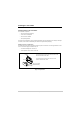
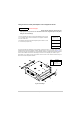
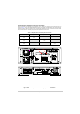
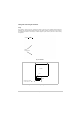
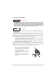
Table Of Contents
- Health and Safety
- Customer Support
- Abbreviations
- Overview
- Specification
- Operation
- Overview
- T6T VHF Amplifier
- Drive Assembly
- Setting Up and Operation
- Normal Operation
- Using the Scroll/Select Switch
- Screen Protocol
- Menu System
- Menu Lock Screen
- Control Screen
- Notes for Setting Up the Transmitter
- Changing the Transmitter’s Operating Frequency
- To Store and Recall Frequency Channels
- To Initiate a BIT Test
- Standby Mode
- Settings
- AM-Voice Settings Procedure
- AM-MSK Mode Settings Procedure
- Mode 2 Settings Screen
- Mode 3 Settings Screen
- Polarities Screen AM-Voice and AM-MSK
- Mode 2 and Mode 3 Polarity Settings
- AM-Voice and AM-MSK BIT Screen
- Mode 2 and Mode 3 BIT Screen
- Software Configuration Screens
- Band Edges
- BIT Status Warning Screens
- Installation
- Warnings and Cautions
- Introduction
- Installing the Transmitter

T6T 300 Watt VHF Transmitter Page 74 Installation
Fitting and Connecting the Combiner
Fitting
The combiner, shown in Fig 15, should be mounted at the back of the cabinet directly behind the
amplifiers’ fans and with the heatsink pointing into the cabinet. Cabinet mounting holes are provided in
the combiner’s bracket to allow fixing to a cabinet upright. Fig 16 shows a plan view of the mounting
arrangement.
Fig 15 Combiner
Fig 16 Combiner Mounting Arrangement Plan View
Cabinet
Mounting Holes
Heatsink
Amplifier
Fans
Combiner
Heatsink
Front of Cabinet
Airflow
Bracket fits to upright
at rear of cabinet