
User's Manual Part 1
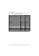
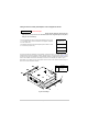
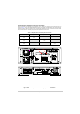
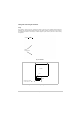
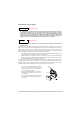
Table Of Contents
- Health and Safety
- Customer Support
- Abbreviations
- Overview
- Specification
- Operation
- Overview
- T6T VHF Amplifier
- Drive Assembly
- Setting Up and Operation
- Normal Operation
- Using the Scroll/Select Switch
- Screen Protocol
- Menu System
- Menu Lock Screen
- Control Screen
- Notes for Setting Up the Transmitter
- Changing the Transmitter’s Operating Frequency
- To Store and Recall Frequency Channels
- To Initiate a BIT Test
- Standby Mode
- Settings
- AM-Voice Settings Procedure
- AM-MSK Mode Settings Procedure
- Mode 2 Settings Screen
- Mode 3 Settings Screen
- Polarities Screen AM-Voice and AM-MSK
- Mode 2 and Mode 3 Polarity Settings
- AM-Voice and AM-MSK BIT Screen
- Mode 2 and Mode 3 BIT Screen
- Software Configuration Screens
- Band Edges
- BIT Status Warning Screens
- Installation
- Warnings and Cautions
- Introduction
- Installing the Transmitter

T6T 300 Watt VHF Transmitter Page 72 Installation
Fitting the Drive Assembly and Amplifiers into an Equipment Cabinet
It is essential that the chosen mechanical installation provides adequate support along the
depth (front to rear) of the unit. The transmitter must not be supported by the front panel;
doing so can cause damage.
The drive assembly and amplifiers can be installed on telescopic slides, or on fixed runners, within a
standard 483 mm (19 inch) equipment cabinet. M4 tapped holes, each 10 mm deep (see Fig 12) are
provided on each side of the equipment to accept the slides. Details of suitable telescopic slides and fixed
runners are available from Park Air. Slide fittings (in this case for an amplifier) are shown in Fig 12.
When fitted in the cabinet, the units’ front panels must be secured to the cabinet’s chassis using four
M6 x 16 mm screws and plastic washers.
Fig 12 Slide Fittings
Caution Mechanical Support
Drive Assembly (2 U)
Amplifier 1 (4 U)
Amplifier 2 (4 U)
Amplifier 3 (4 U)
The drive assembly and the three associated amplifiers, which occupy
14 U of cabinet space, should be installed in an equipment cabinet in
the order shown here.
The amplifiers are identical and are designated by the numbers 1, 2 and
3 for connection purposes only.
3
4
2
1
M4 x 8 mm Half Head Bolt
M4 Wavy Washer
Inner Slide
Transmitter
Description
4
3
2
1
Item
Item Description
1
2
3
4
Amplifier
Inner slide
M4 wavy washer
M4 x 8 mm half-head bolt