
User's Manual Part 1


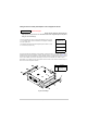
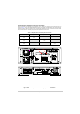
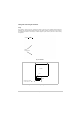
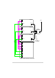
Table Of Contents
- Health and Safety
- Customer Support
- Abbreviations
- Overview
- Specification
- Operation
- Overview
- T6T VHF Amplifier
- Drive Assembly
- Setting Up and Operation
- Normal Operation
- Using the Scroll/Select Switch
- Screen Protocol
- Menu System
- Menu Lock Screen
- Control Screen
- Notes for Setting Up the Transmitter
- Changing the Transmitter’s Operating Frequency
- To Store and Recall Frequency Channels
- To Initiate a BIT Test
- Standby Mode
- Settings
- AM-Voice Settings Procedure
- AM-MSK Mode Settings Procedure
- Mode 2 Settings Screen
- Mode 3 Settings Screen
- Polarities Screen AM-Voice and AM-MSK
- Mode 2 and Mode 3 Polarity Settings
- AM-Voice and AM-MSK BIT Screen
- Mode 2 and Mode 3 BIT Screen
- Software Configuration Screens
- Band Edges
- BIT Status Warning Screens
- Installation
- Warnings and Cautions
- Introduction
- Installing the Transmitter

T6T 300 Watt VHF Transmitter Page 71 Installation
Installing the Transmitter
Initial Inspection of the Transmitter
The transmitter comprises:
❑ One T6T VHF drive assembly
❑ Three T6T VHF amplifiers
❑ One T6T VHF combiner
❑ One phasing harness.
On receipt of the transmitter, remove all transit packaging and check that there is no damage. If damage
is evident, contact Park Air immediately and retain the original transit packaging.
Fitting the Correct ac Input Fuses
The mains input fuses are an integral part of the rear panel ac connectors. The fuse type must be correct
for the local mains supply as detailed in Fig 11.
❑ The drive assembly has one fuse, F2
❑ Each amplifier has two fuses, F3 and F4.
Fig 11 ac Input Fuses
FS2
Spare Fuse
Line
Neutral
Earth
For a mains input in the range 110 to 240 Vac, fuses F3 and
F4 should be rated T6.3AH, 250V.
For a mains input in the range 110 to 24
0 Vac, fuse F2
should be rated T3.15AH, 250V.
F3 and F4 (amplifier)
Holder for spare
fuse (not supplied)
F2 (drive assembly)