
User's Manual Part 1
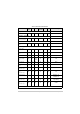
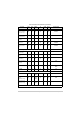
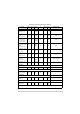


Table Of Contents
- Health and Safety
- Customer Support
- Abbreviations
- Overview
- Specification
- Operation
- Overview
- T6T VHF Amplifier
- Drive Assembly
- Setting Up and Operation
- Normal Operation
- Using the Scroll/Select Switch
- Screen Protocol
- Menu System
- Menu Lock Screen
- Control Screen
- Notes for Setting Up the Transmitter
- Changing the Transmitter’s Operating Frequency
- To Store and Recall Frequency Channels
- To Initiate a BIT Test
- Standby Mode
- Settings
- AM-Voice Settings Procedure
- AM-MSK Mode Settings Procedure
- Mode 2 Settings Screen
- Mode 3 Settings Screen
- Polarities Screen AM-Voice and AM-MSK
- Mode 2 and Mode 3 Polarity Settings
- AM-Voice and AM-MSK BIT Screen
- Mode 2 and Mode 3 BIT Screen
- Software Configuration Screens
- Band Edges
- BIT Status Warning Screens
- Installation
- Warnings and Cautions
- Introduction
- Installing the Transmitter

T6T 300 Watt VHF Transmitter Page 70 Installation
Fuses and Connectors
The following list details the equipment supply fuses and connectors. Some of the connectors (depending
on your particular configuration) are required during installation.
Table 14 Fuses and Connectors
Component Type Park Air Part Number
Fuses:
AC input fuses, F3 and F4 for 110-240 V input
AC input fuse, F2 for 110-240 V input
T6.3AH, 250V
T3.15AH, 250V
29L01170108S
29C01100102S
DC input fuses, F1 (drive assembly), F1 and F2 (amplifier) 15A size 0 29-01350201
Connectors:
AC supply connectors IEC 20-02030102
DC supply connectors XLR 3-pin 20-01030106
Antenna connector N-type plug 19-01030301
MARC connector 9-way D-type plug Plug: 20-01090100
Cover: 20-09090101
MARC audio RJ48 plug 20K01080100
MARC data RJ48 plug 20K01080100
Facilities connector 15-way D-type plug Plug: 20-01150100
Cover: 20-09150101
HDLC connector RJ48 plug 20K01080100
T1/E1 connector RJ48 plug 20K01080100
Reference connector SMB connector 19C01050300
Microphone/Diagnostics connector 7-pin DIN plug 20-01070101