
User's Manual Part 1
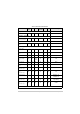
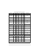
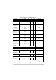


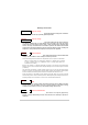
Table Of Contents
- Health and Safety
- Customer Support
- Abbreviations
- Overview
- Specification
- Operation
- Overview
- T6T VHF Amplifier
- Drive Assembly
- Setting Up and Operation
- Normal Operation
- Using the Scroll/Select Switch
- Screen Protocol
- Menu System
- Menu Lock Screen
- Control Screen
- Notes for Setting Up the Transmitter
- Changing the Transmitter’s Operating Frequency
- To Store and Recall Frequency Channels
- To Initiate a BIT Test
- Standby Mode
- Settings
- AM-Voice Settings Procedure
- AM-MSK Mode Settings Procedure
- Mode 2 Settings Screen
- Mode 3 Settings Screen
- Polarities Screen AM-Voice and AM-MSK
- Mode 2 and Mode 3 Polarity Settings
- AM-Voice and AM-MSK BIT Screen
- Mode 2 and Mode 3 BIT Screen
- Software Configuration Screens
- Band Edges
- BIT Status Warning Screens
- Installation
- Warnings and Cautions
- Introduction
- Installing the Transmitter

T6T 300 Watt VHF Transmitter Page 69 Installation
Introduction
The procedures necessary to install a transmitter are listed in Table 13. Installation is in two parts: Steps
1 to 9 in Table 13 must be completed irrespective of how the transmitter is to be configured; step 10
provides a selection of different configurations.
.
Table 13 Installation Procedures
Step Procedure Reference
1 Read and understand the warnings and cautions given on page 68.
2 Perform an initial inspection of the transmitter and fit the correct ac input fuse. page 71
3 Fit the drive assembly and amplifiers into an equipment cabinet. page 72
4 Connect the amplifiers to the drive assembly. page 73
5 Fitting and connecting the combiner. page 74
6 Connect the antenna. page 75
7 Connect the chassis stud to the cabinet or system earth. page 77
8 Connect the dc input supply (if required). page 77
9 Connect the ac input supply (if required). page 78
10 Configuring the transmitter for operational use. page 79