
User's Manual Part 1
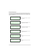
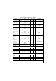


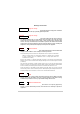
Table Of Contents
- Health and Safety
- Customer Support
- Abbreviations
- Overview
- Specification
- Operation
- Overview
- T6T VHF Amplifier
- Drive Assembly
- Setting Up and Operation
- Normal Operation
- Using the Scroll/Select Switch
- Screen Protocol
- Menu System
- Menu Lock Screen
- Control Screen
- Notes for Setting Up the Transmitter
- Changing the Transmitter’s Operating Frequency
- To Store and Recall Frequency Channels
- To Initiate a BIT Test
- Standby Mode
- Settings
- AM-Voice Settings Procedure
- AM-MSK Mode Settings Procedure
- Mode 2 Settings Screen
- Mode 3 Settings Screen
- Polarities Screen AM-Voice and AM-MSK
- Mode 2 and Mode 3 Polarity Settings
- AM-Voice and AM-MSK BIT Screen
- Mode 2 and Mode 3 BIT Screen
- Software Configuration Screens
- Band Edges
- BIT Status Warning Screens
- Installation
- Warnings and Cautions
- Introduction
- Installing the Transmitter

T6T 300 Watt VHF Transmitter Page 68 Installation
Warnings and Cautions
The instructions given in this topic involve connecting dangerous voltage to the transmitter
and should be carried out only by suitably qualified personnel.
The equipment is permanently connected to the mains supply when the mains connectors
are attached. Switching the rear panel Supply switch to off does not isolate all internal
circuits from the mains supply. For this reason, a mains isolating switch should be fitted
close to, and easily accessible from, the transmitter's position. The isolation switch should
isolate both live and neutral supplies to the IEC connectors fitted to the drive assembly and
amplifiers, be clearly labelled, and adequately rated to protect the equipment.
The antenna used with the transmitter must be installed such that the resultant radiated field
strength is below 10 W/m² in areas normally accessible to personnel.
The RF field strength from the antenna can be predicted from the equation S=1.4PG/4πR
2
[Where S = power density; P = power input to antenna; G = antenna gain; R = distance
to centre of radiation and 1.4 = multiplication factor for average power based on a
modulation index of 90%.]
Based on this formula for a 300 watt transmitter and using a 0 dBi antenna, the predicted safe
distance from the centre of radiation would be approximately 1.8 m for a field strength of 10 W/m
2
(1 mW/cm
2
).
This meets the requirements of Health Canada Safety Code 6 for RF and microwave exposed
workers. For persons not classed as RF and microwave workers and including the general public
the limit is 2 W/m
2
(0.2 mW/cm
2
) which increases the minimum safe distance to 4.1 m.
Further information on calculating the field strengths and power levels can be found in Health
Canada Safety Code 6 'Limits of Human Exposure to Radiofrequency Electromagnetic Fields in the
Frequency Range 3 kHz to 300 GHz', and also in FCC document OET Bulletin 65.
The T6T transmitter's circuitry contains Electrostatic Sensitive Devices (ESDs). Personnel
must be aware of the precautions necessary to prevent damage to such devices. During
installation all precautions necessary to prevent ESD damage must be taken.
Changes or modifications made to this equipment that are not expressly approved by
Park Air, or parties authorized by Park Air, could void the user’s authority to operate the
equipment.
WARNING Dangerous Voltage
WARNING Dangerous Voltage
WARNING
Antenna Radiation
Caution
ESDs
Caution Unauthorized Modifications