
User's Manual Part 1
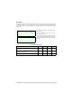
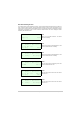
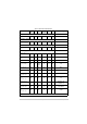
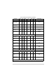
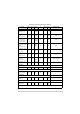


Table Of Contents
- Health and Safety
- Customer Support
- Abbreviations
- Overview
- Specification
- Operation
- Overview
- T6T VHF Amplifier
- Drive Assembly
- Setting Up and Operation
- Normal Operation
- Using the Scroll/Select Switch
- Screen Protocol
- Menu System
- Menu Lock Screen
- Control Screen
- Notes for Setting Up the Transmitter
- Changing the Transmitter’s Operating Frequency
- To Store and Recall Frequency Channels
- To Initiate a BIT Test
- Standby Mode
- Settings
- AM-Voice Settings Procedure
- AM-MSK Mode Settings Procedure
- Mode 2 Settings Screen
- Mode 3 Settings Screen
- Polarities Screen AM-Voice and AM-MSK
- Mode 2 and Mode 3 Polarity Settings
- AM-Voice and AM-MSK BIT Screen
- Mode 2 and Mode 3 BIT Screen
- Software Configuration Screens
- Band Edges
- BIT Status Warning Screens
- Installation
- Warnings and Cautions
- Introduction
- Installing the Transmitter

T6T 300 Watt VHF Transmitter Page 66 Operation
STANDBY
Enter and exit
standby facility
✔✔✔ ✔ ✗✗ Not in Standby
SOFTWARE CONFIGURATION
View the
transmitter’s
software
configuration
✔✔ ✗ ✗ ✔✔
-
LOCK FACILITIES
Front panel lock
✗✔✗ ✗ ✗✗
Off
MARC lock
✗✔✗ ✗ ✗✗
Off
T1/E1 lock
✗✔✗ ✗ ✗✗
Off
HDLC lock
✗✔✗ ✗ ✗✗
Off
Table 12 Functions and Parameters (Continued)
Function Front
Panel
VFP MARC T6
Controller
T1/E1 HDLC Default Setting